I’m going to make shaders and procedural environments… Let’s learn how!
Starting Tasks.
The plan for the first few weeks of development going to be learning the required knowledge for shader dev and procedural environments. As well as some other tasks for the planning of the project.
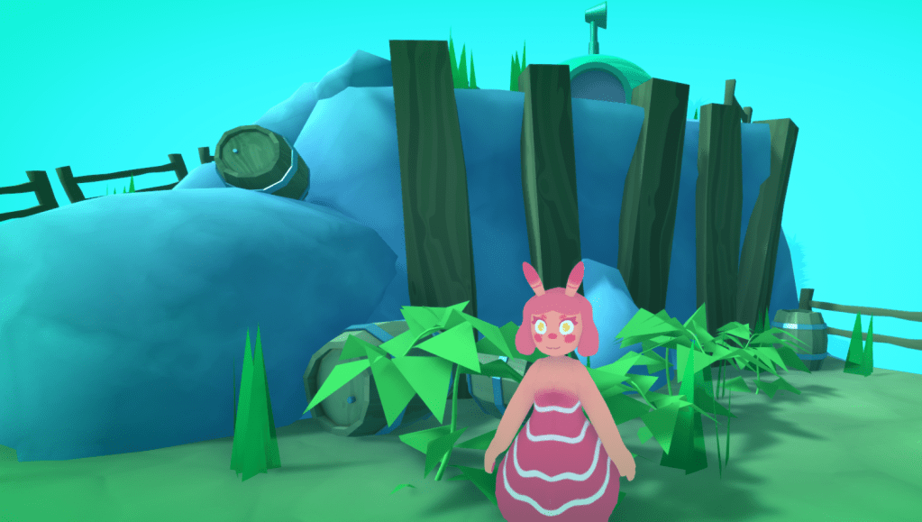
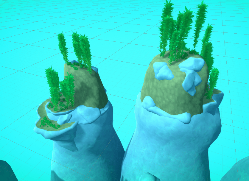
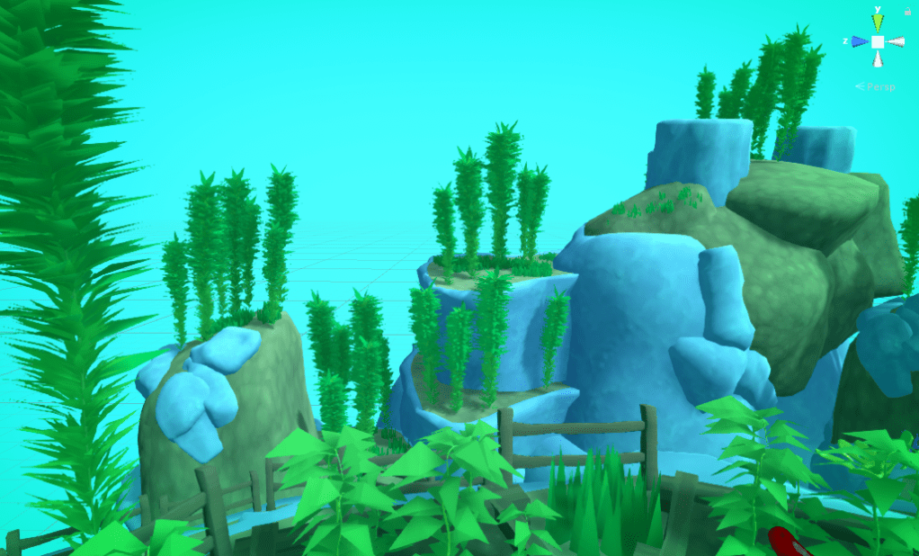
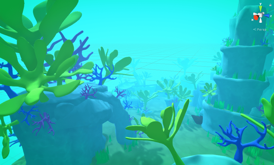
To make the world seem a little more alive I wanted to add some background environment pieces that can be seen off in the distance.
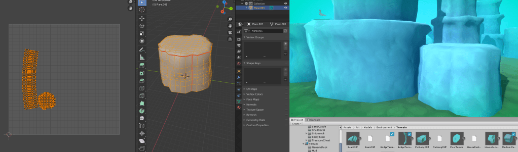
I created a base for these pieces in blender, ensuring they were all very tall so the fog would blend out their bases. I created Two pieces one for rock, and one for dirt.
Combining them with some other assets form the project I created some simple backing pieces.
As you can see The shapes a a lot simpler than the more detailed pieces, but as they are only going to be able to be seen from far away and partially covered by fog it doesn’t matter to much.
Simple blockey environment piece.
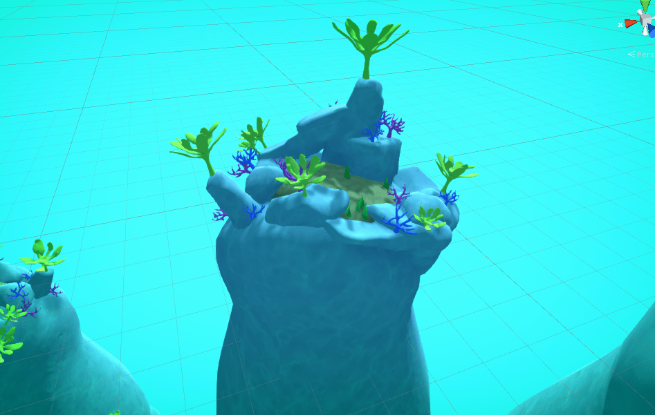
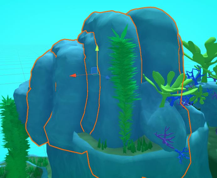
Below are all the background pieces I created.
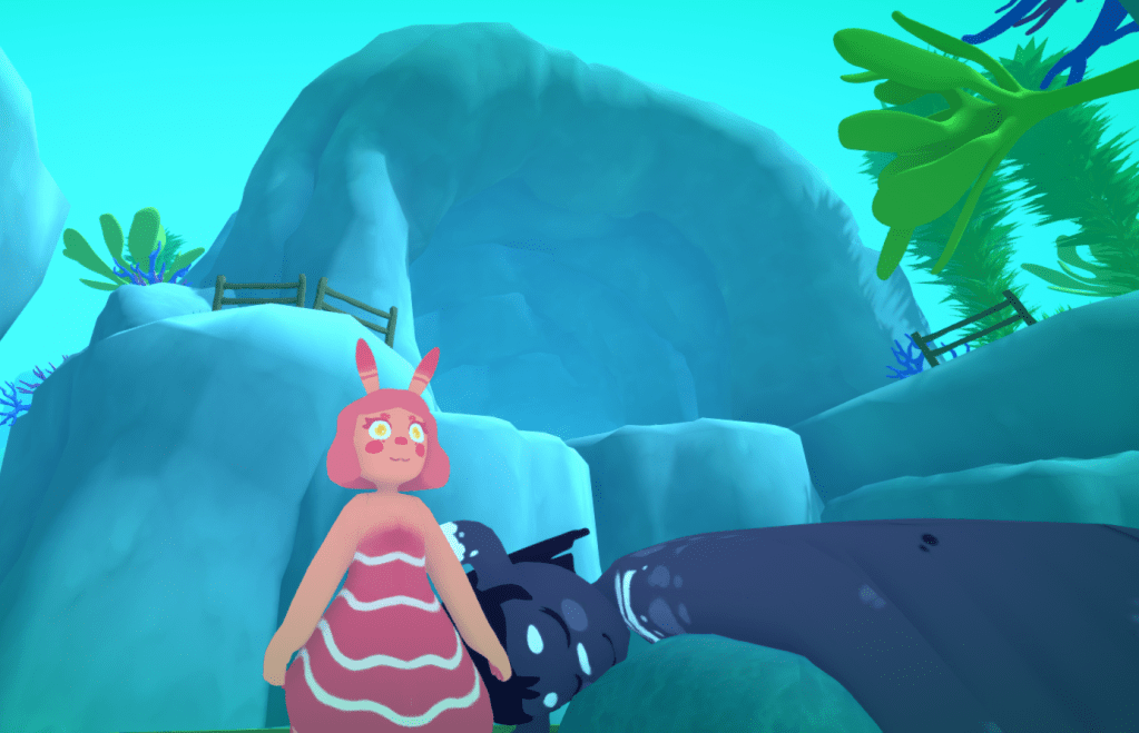
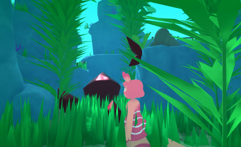
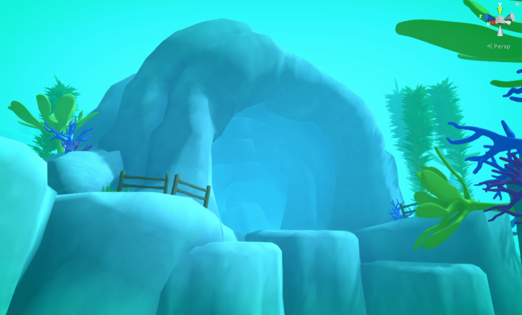
Finally I grouped together a load or archways to create a cave.
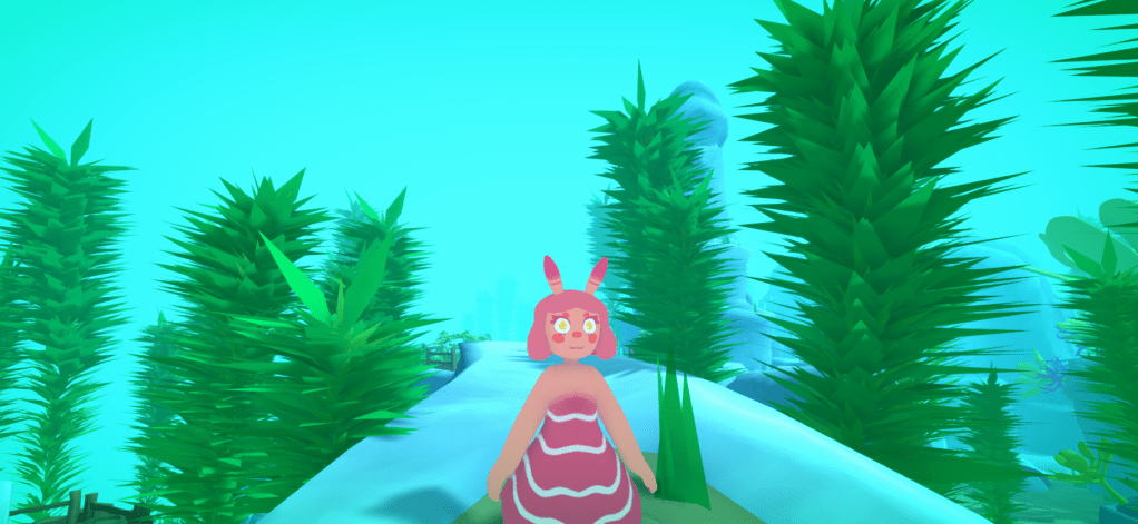
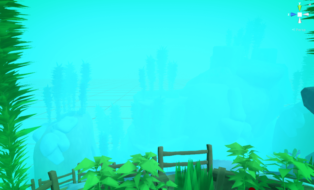
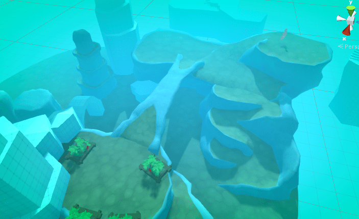
The fog is important for these pieces. It stops the player from focusing on them too much.
With ought fogWith Fog. The whole scene with ought fog.
This is me documenting any decisions I make while producing the final environmental art assets for going home.
The pipeline I created for these assets is detailed along with the research I did in my blog post Here.
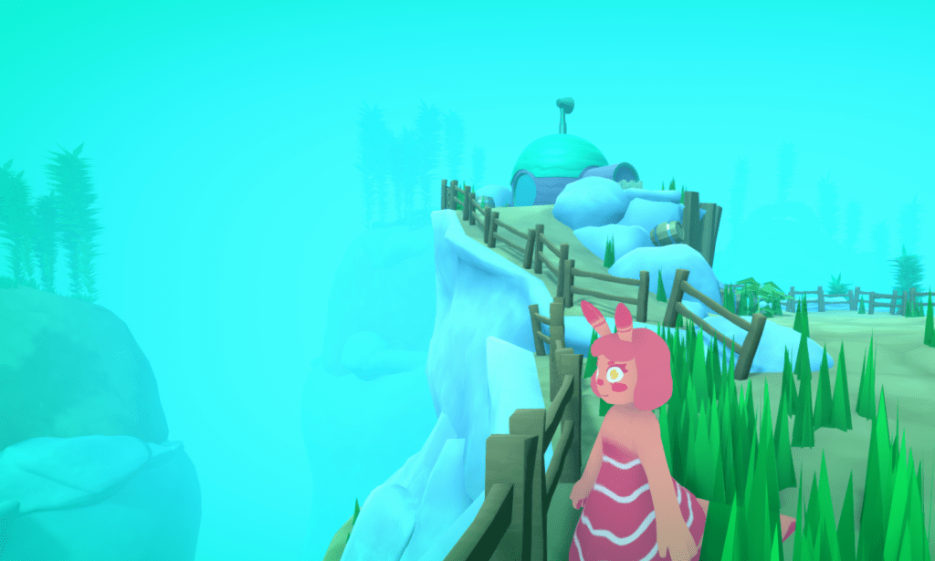
Starting to replace the grey-box.
Nearly finished.
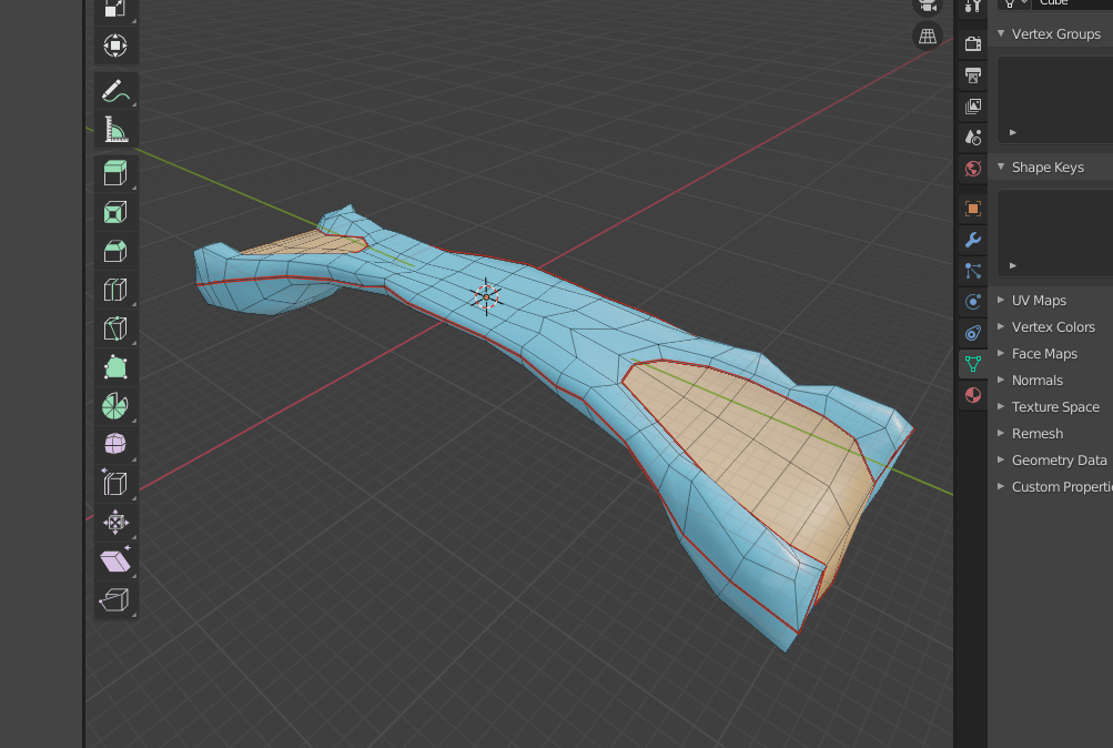
Bridge and the bean area added. The bridge topology In Blender.
Finished
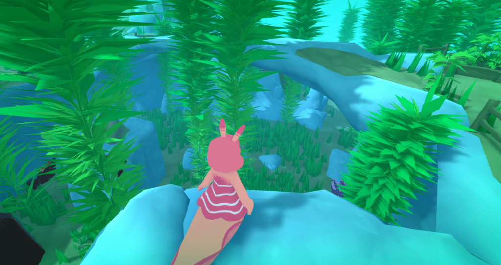
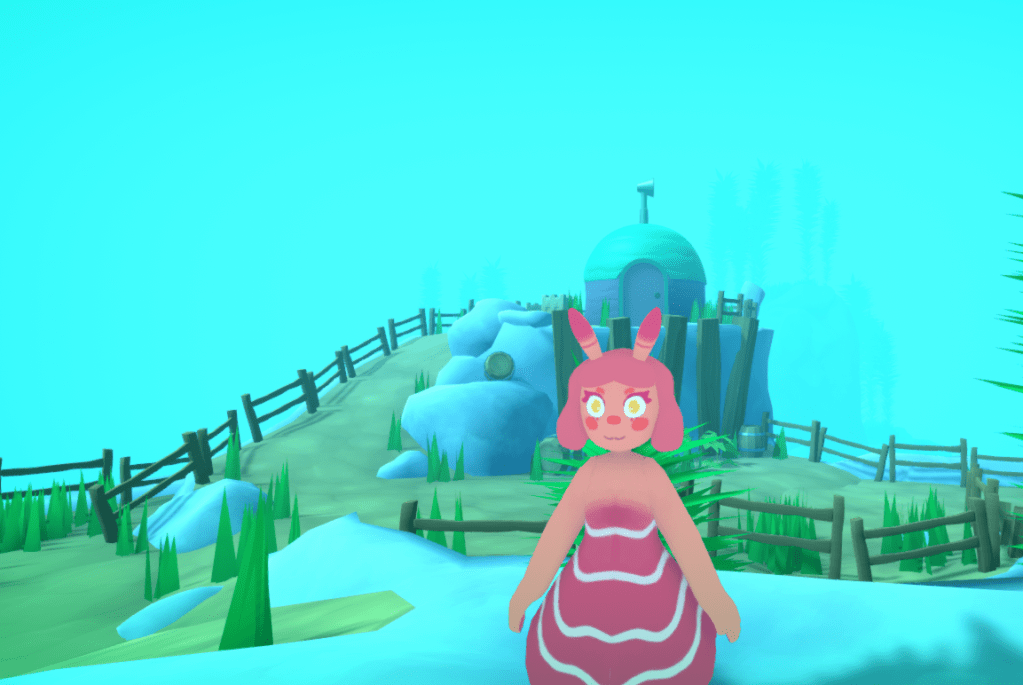
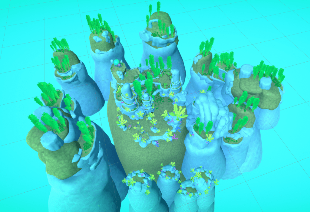
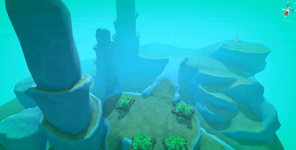
All the terrain assets complete.
A giff flying around the finished initial terrain assets.
Megan created the small arch and small and medium flat rock assets. All the rest are my work.
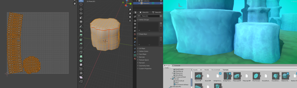
The plan now is to add the supporting props to help flesh out the scene. I have also been scaling some of the UV’s in blender to make the textures more uniform.
Before Scaling.After Scaling.
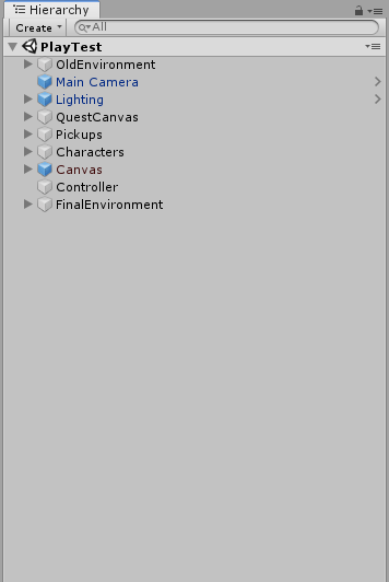
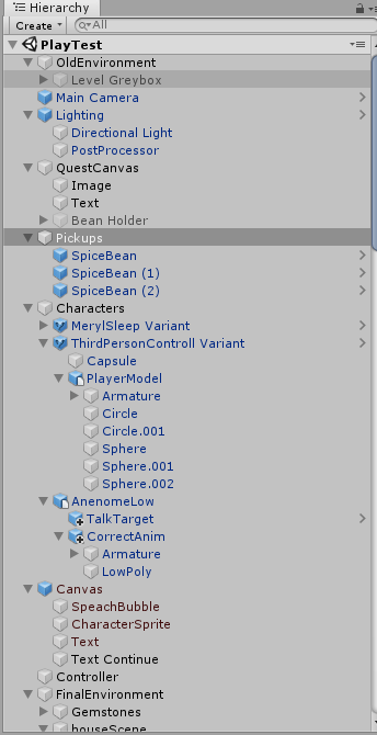
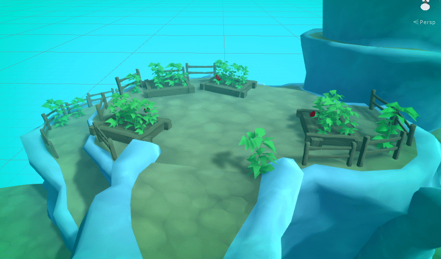
After this I started placing a lot of props to populate the scene. I made sure to organize the Hierarchy by grouping game object under empty parent game objects. So I could minimize groups of environment objects in the hierarchy, maintaining a quick workflow in the long run.
To illustrate how hard it is to navigate a badly organised hierarchy. This is the hierarchy expanded vs fully closed up.
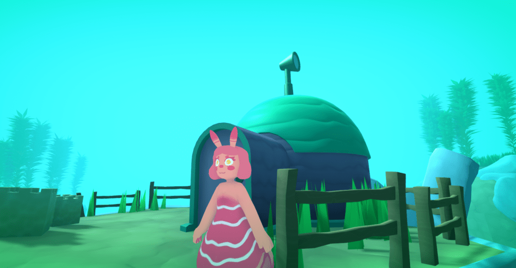
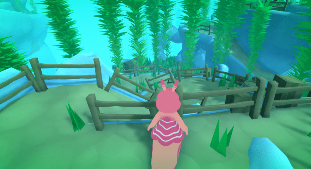
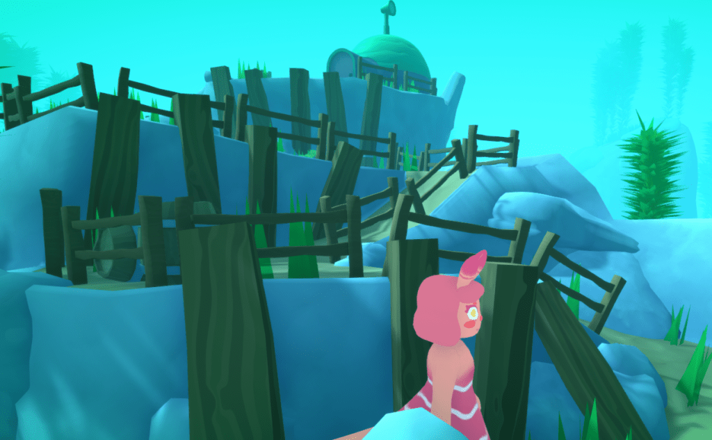
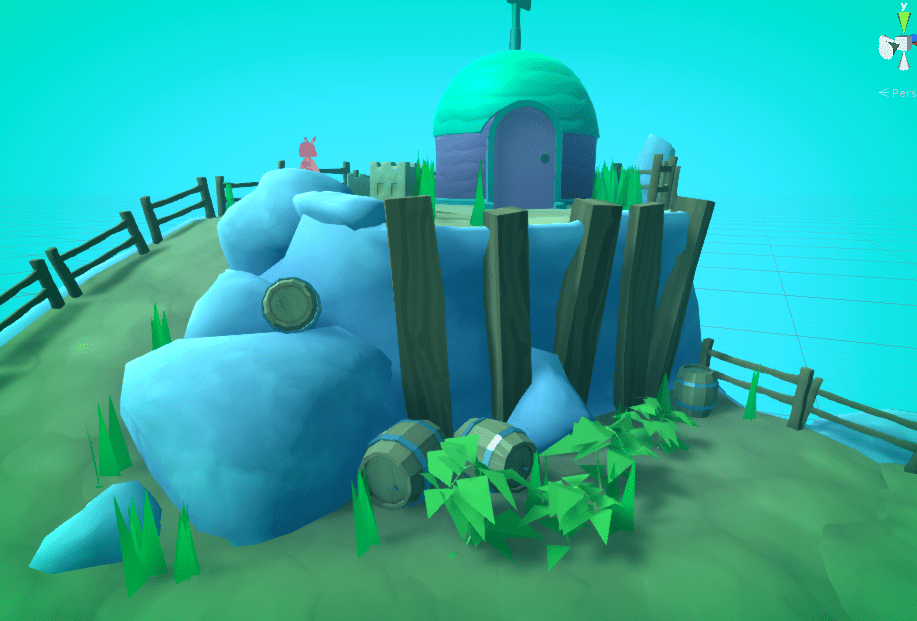
Nice and neat. And it continues with what would be another 3 screenshots.House area. first V1.Fences…
While adding the props I also tweaked the material settings as I went along to create a better cohesion to the scene. Examples below.
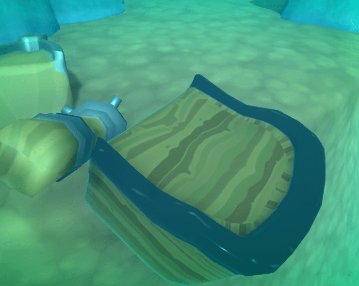
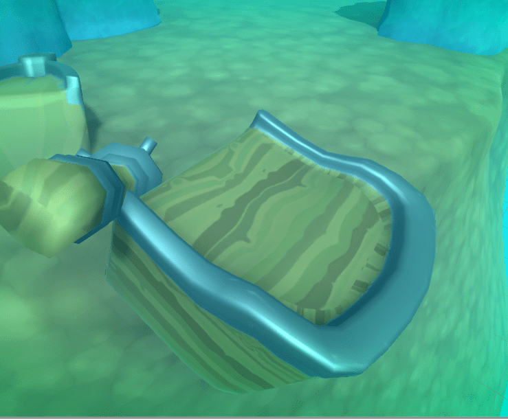
Here the material on baileys is way to shiny in comparison to the rest of the scene so the lighting looks off.
before.
With the smoothness (value that controls how shiny a material is) turned down, the peice is much more cohesive. The metal also looks more realistic as a fully smooth metal is a mirror like material.
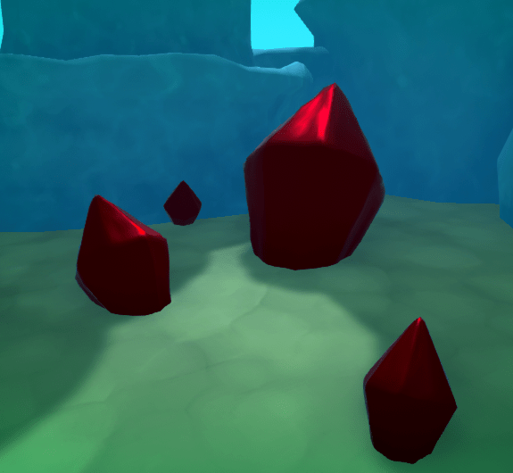
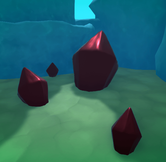
Here on the gemstones the red is way to intense.
Before.
With the saturation turned down the material looks much more realistic.
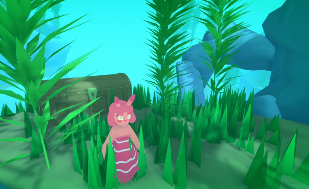
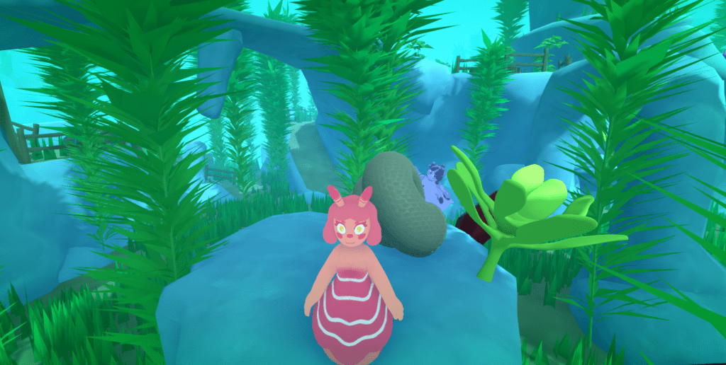
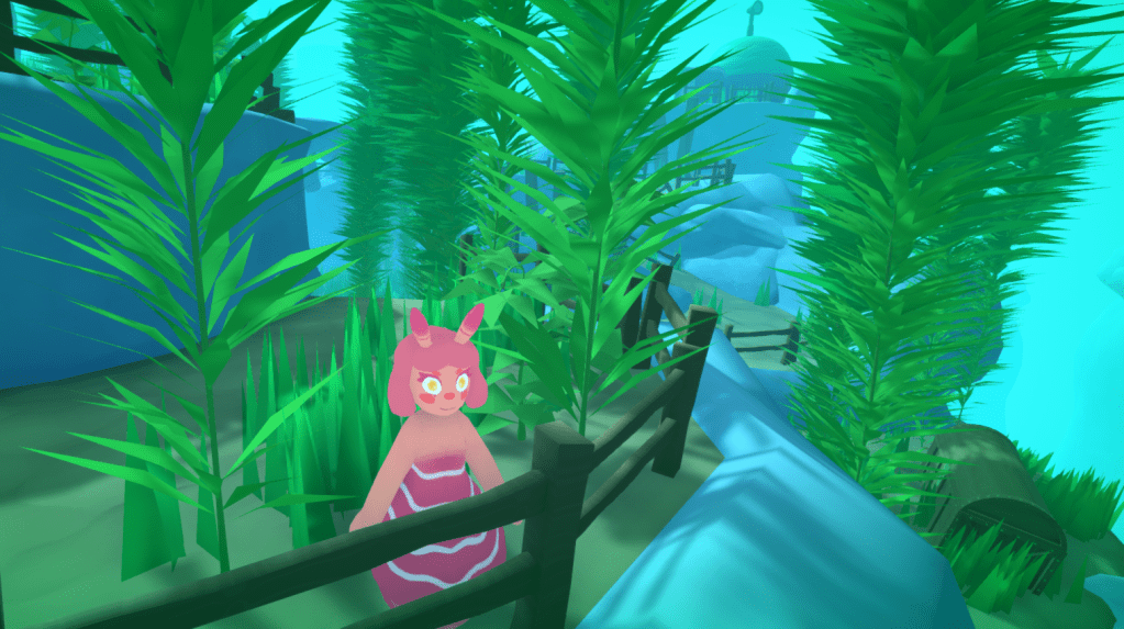
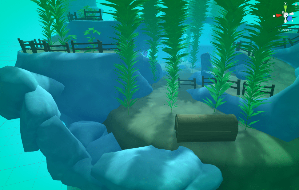
Here is just a screenshot montage as the level develops.
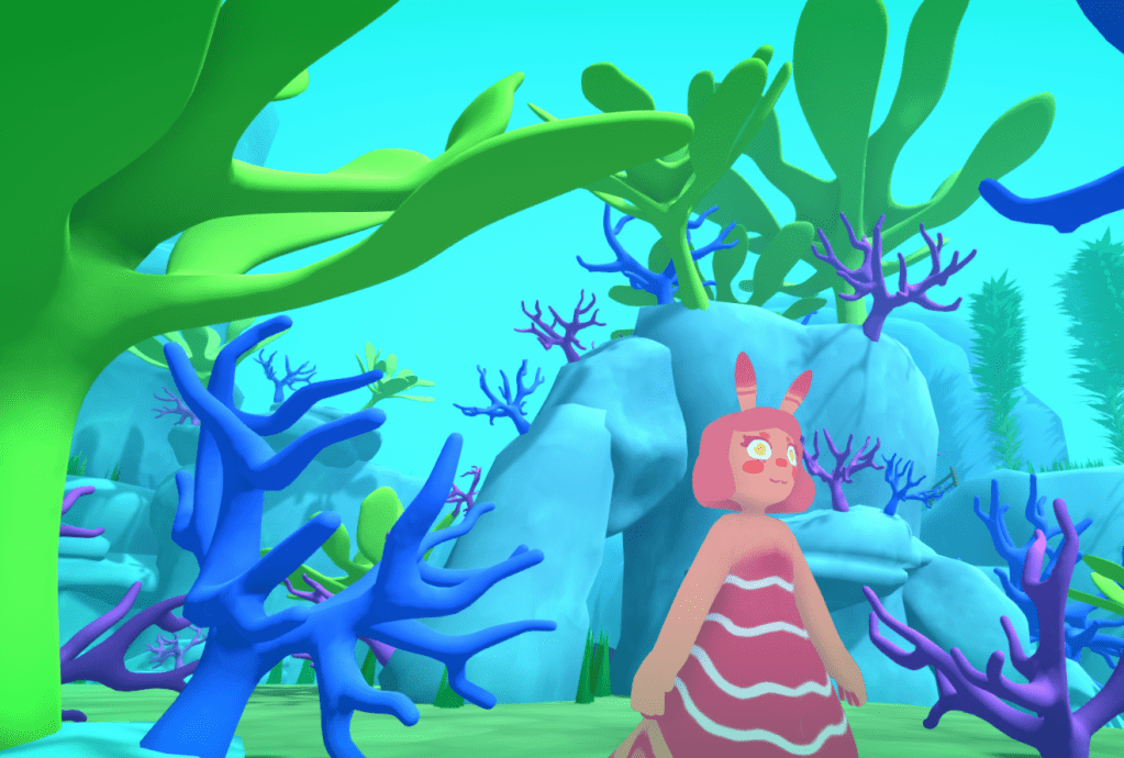
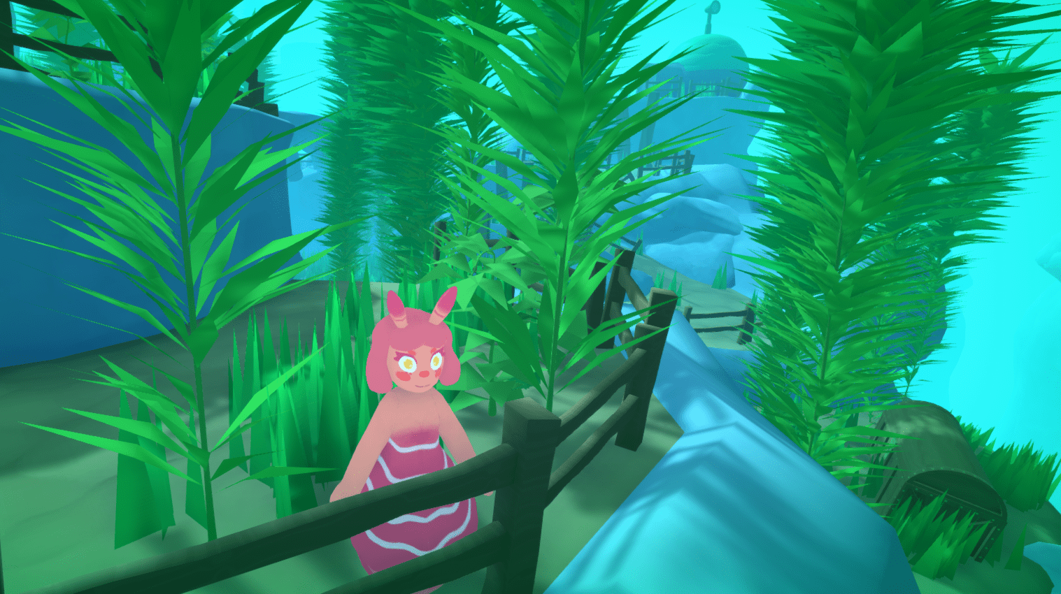
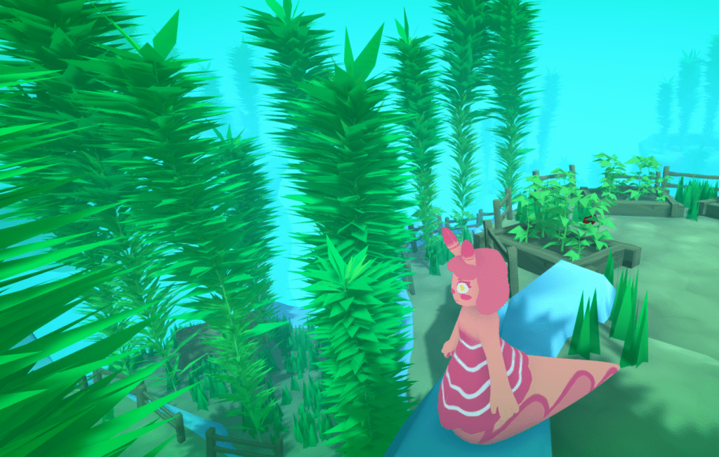
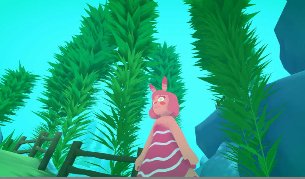
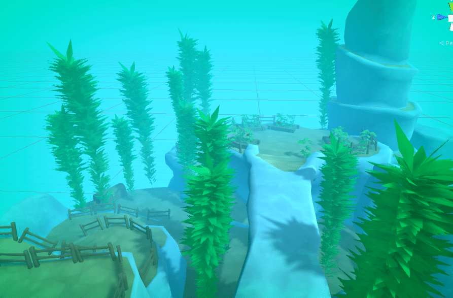
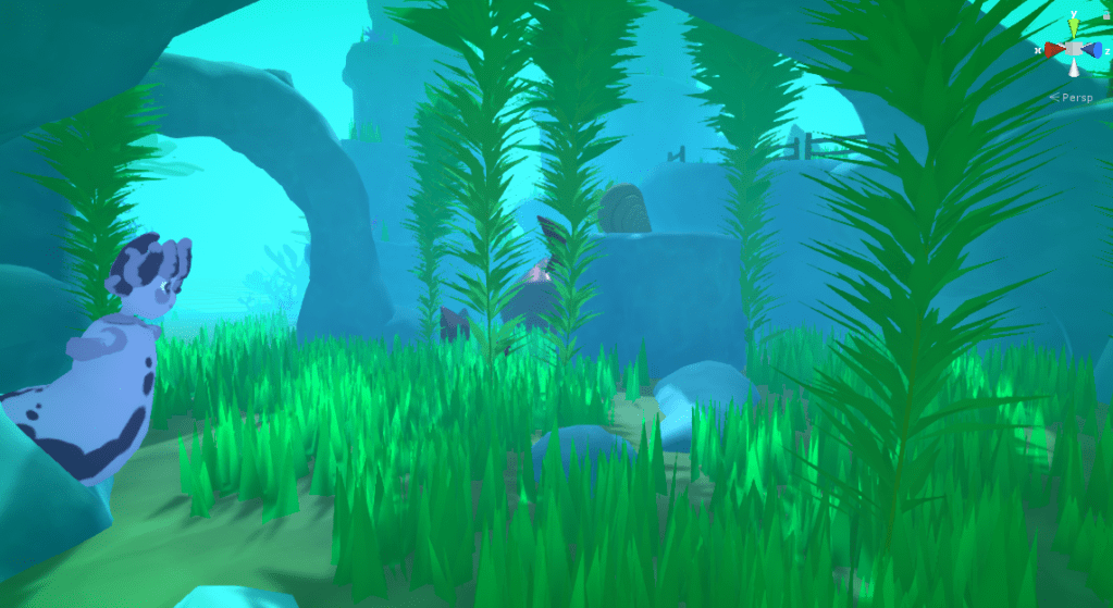
More bean plants because they are pretty!Adding Kelp Plants.
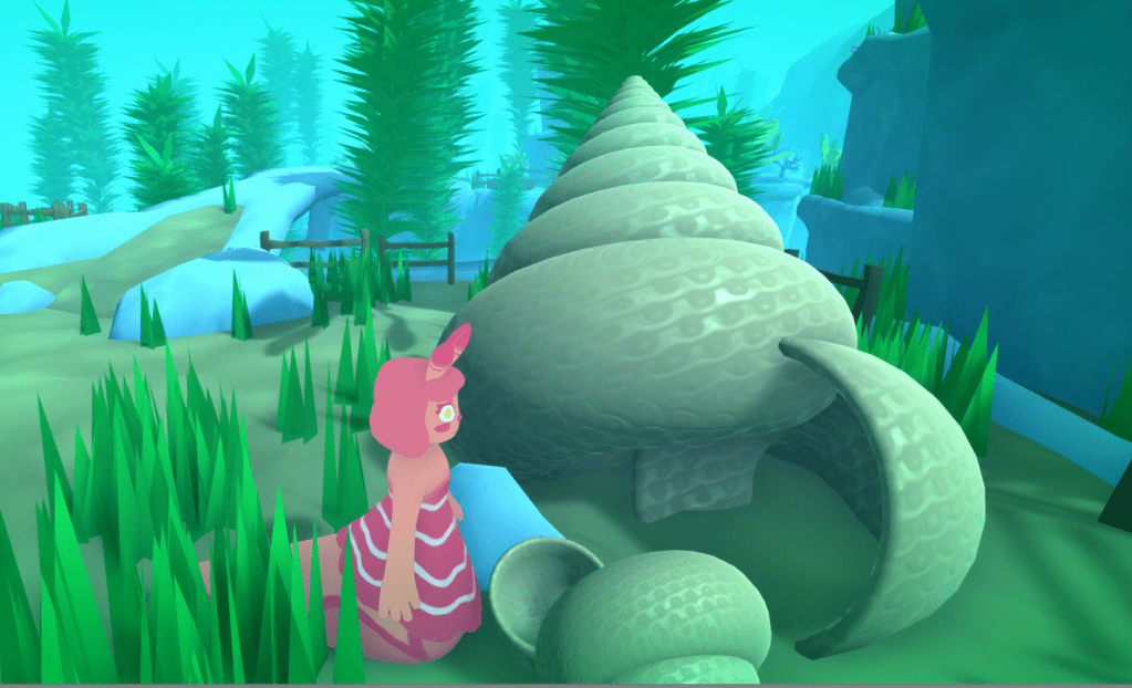
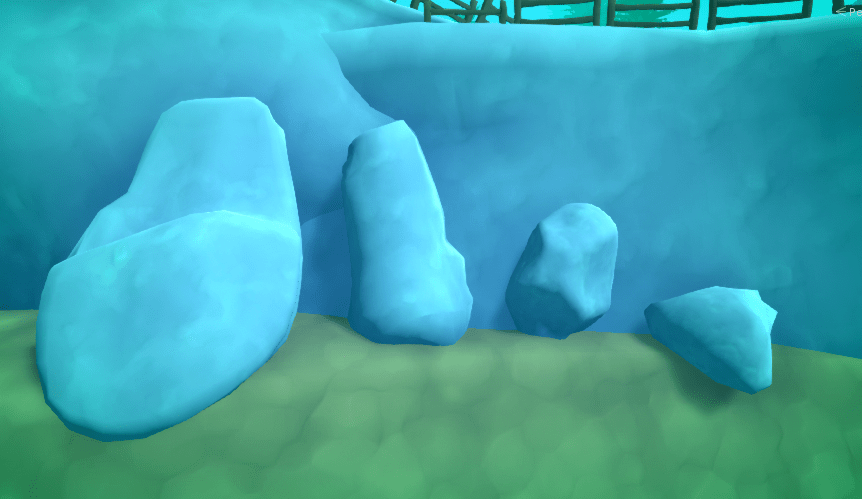
Me and Megan modeled some rocks, the 2nd leftmost is Megans, the rest are mine.
These will be used to add variety and a more natural look, to the scenes environment.
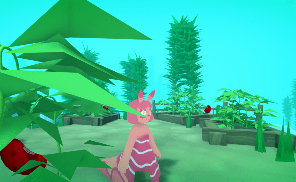
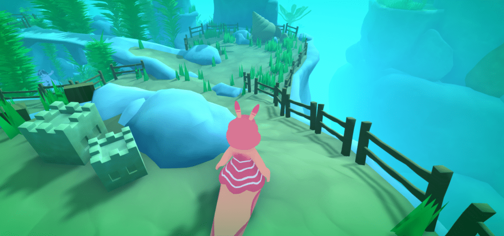
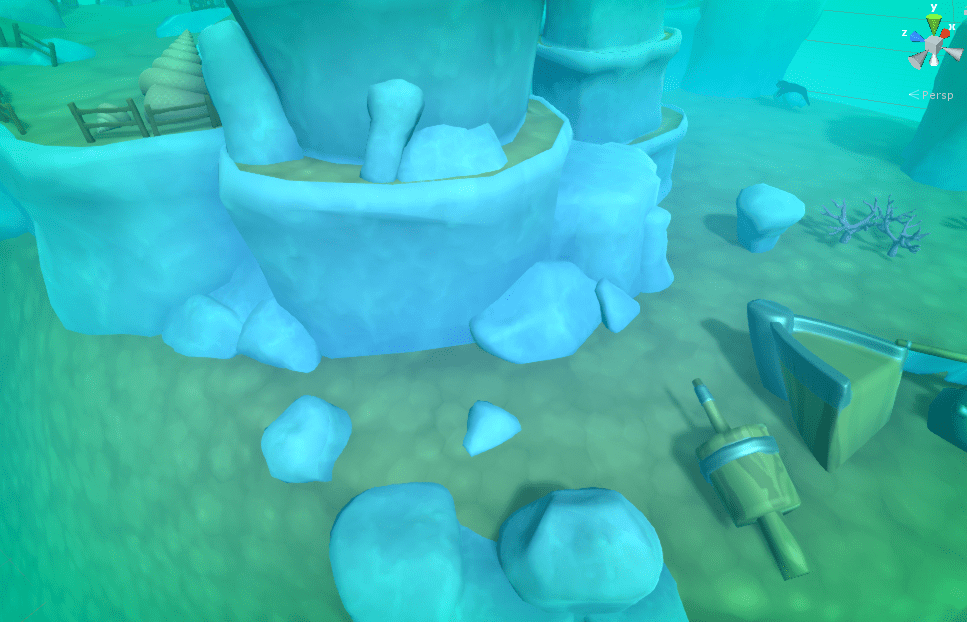
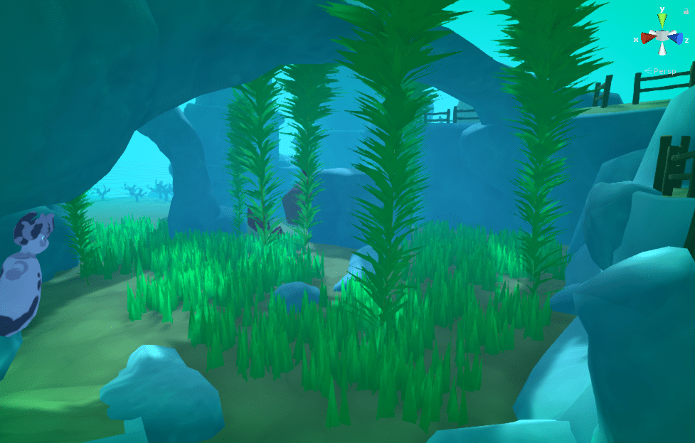
Extra Rock props. Adding Rocks to the scene.More RocksGrass time!Using Bean plants cemented in the ground as weeds. Coral.
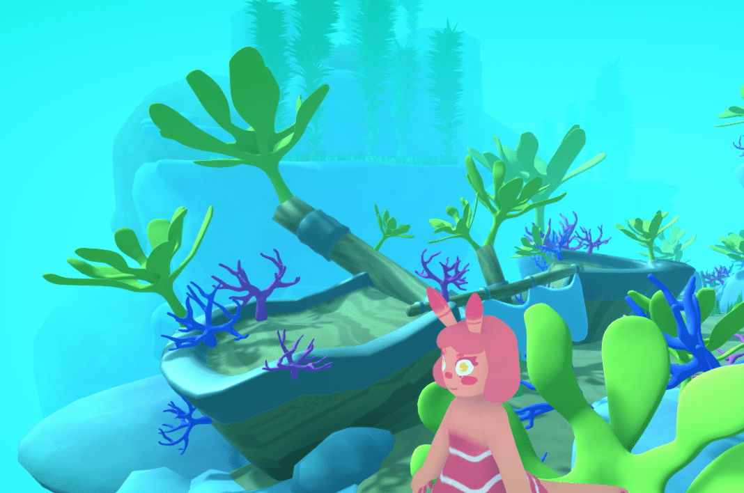
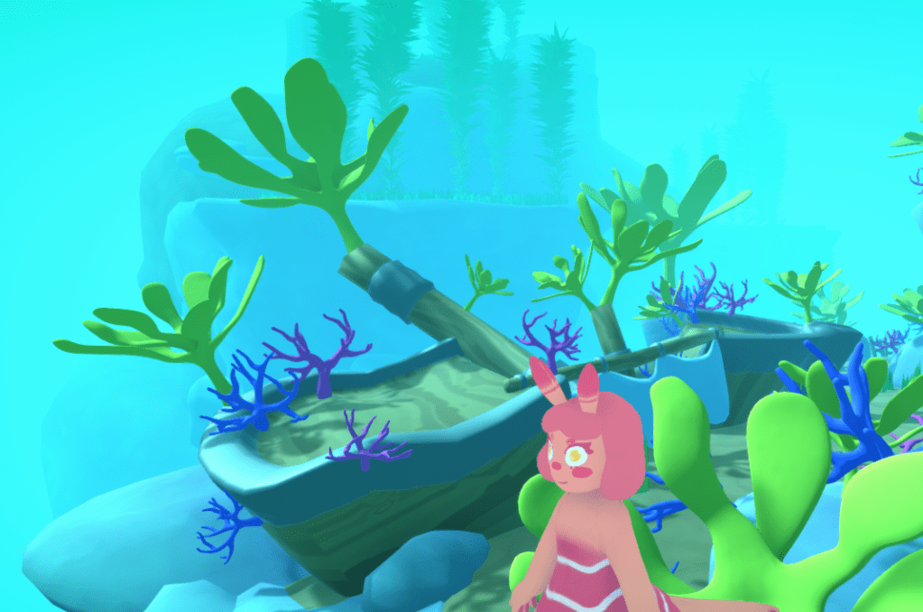
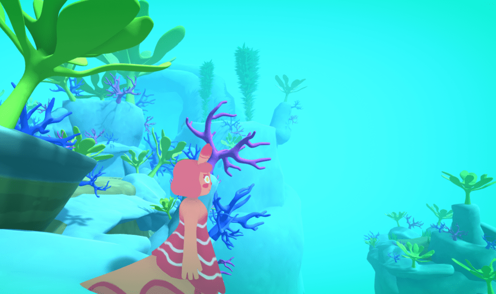
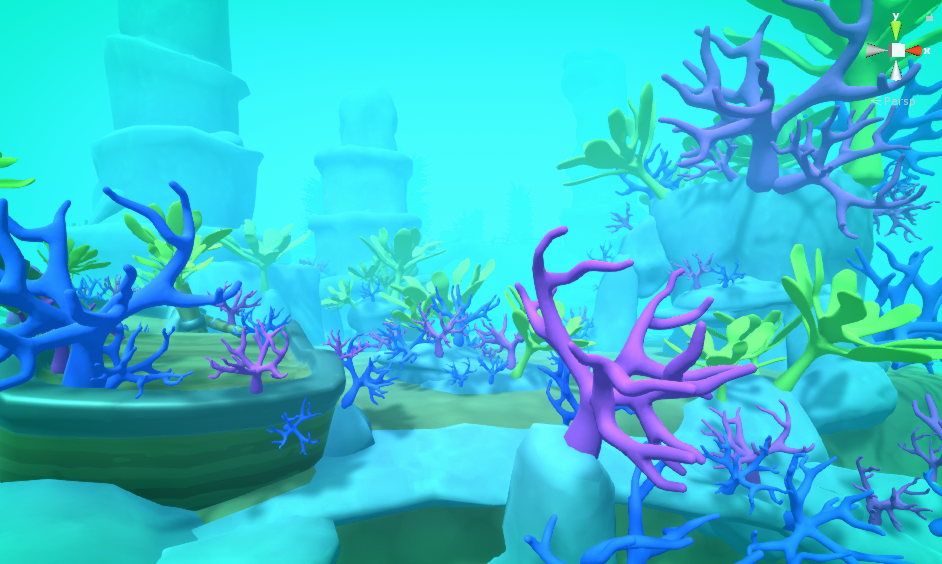
A note on coral.
I was never really happy with the outcome of the reef. The post processing really disrupted the colours on the coral and gave me a very limited colour palette to work with. In the end I ended up with the screenshot above. Which I think looks OK. I wish I had more time to model more coral models for the project.
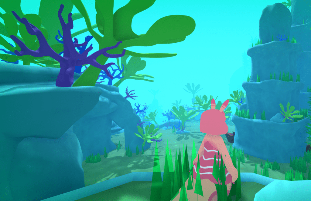
Coral With grass
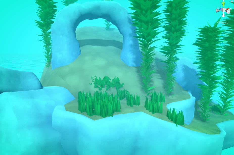
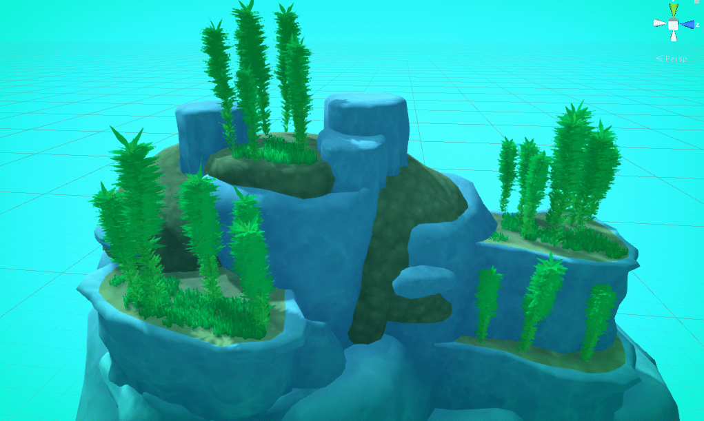
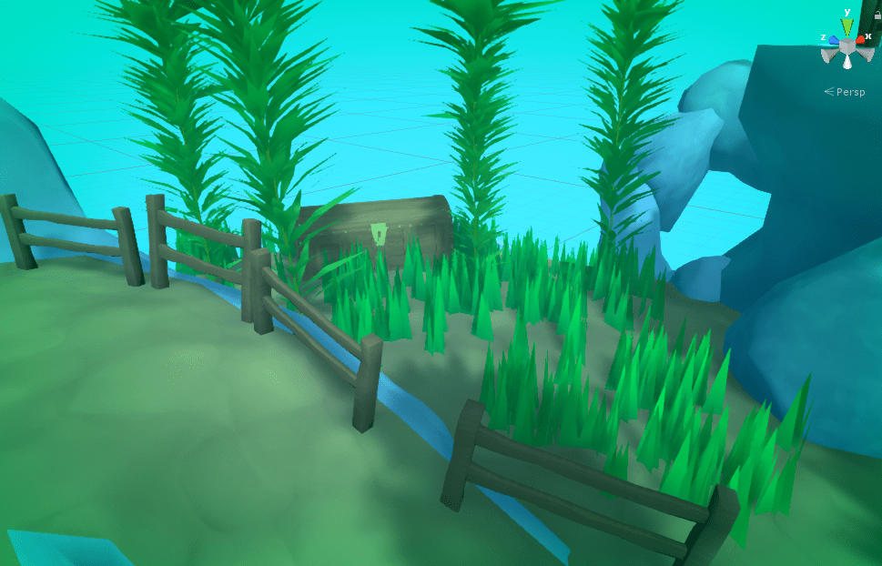
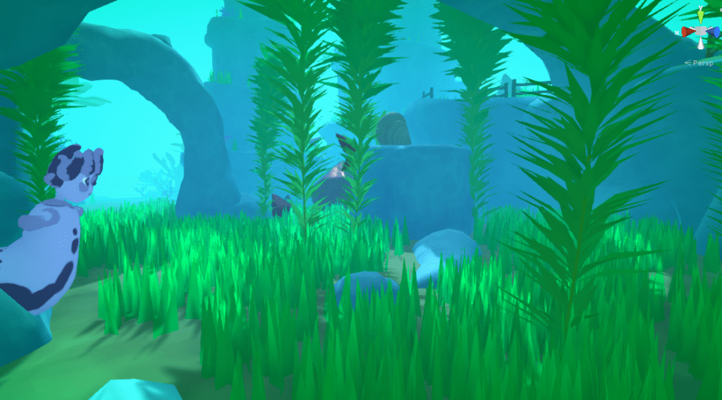
I wanted to add some variance to the grass. This is a before and after shot. I did this by selecting grass randomly form the hierarchy and scaling them up. (Which in turn effects the height of the generated grass blades)
BeforeAfter
Subtle difference, but I think it makes the grass look much more natural.
This illustrates the use of Unity’s hierarchy selection. But is probably more useful as a demonstration of why good hierarchy management is important.
Long
Now the level was nearing completion aesthetically It was time to move on to refining the game-play (and fixing some bug we needed to get rid of so we could build the game)
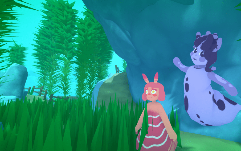
One problem with the level was that now Doreen was much harder to see. But this post is already gigantic. So I will address this in another post. There will also be beauty shots under the showcase section of the blog once I am finished.
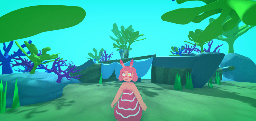
To help bring the character to life I wanted to introduce an idle animation for Doreen. My plan was to create something inspired by anemones and to help put fun friendly feel to the character.
I had the Idea to make hers arms wave like an anemones tentacles in the ocean, But to also make her movements kind of like a dance to give her a humanoid character to her to make her more approachable.
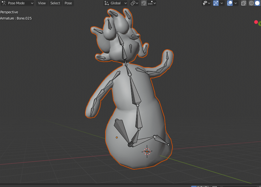
I had her rigged from when I initially made her character. However the root of the bones was at the neck of her model, which made it hard to animate the entire body like I would want as I wanted to animation to start from the base of her body. So naturally the first step was to re-rig the mesh.
The new rig.
As you can see the root now starts from the base of her “spine” down near her tail.
I tried to create the animations with as few bone movements as possible, so they would be easy to tweak. Especially as I was planning to use curves later on to help with the feel of the animation.
There ended up being 3 main parts of the model to animate.
The Body swinging from side to side.
2. The arms waving up and down.
3. her head bobbing from side to side.
I started with the body as this would be the root cause of most of the motion. To create the motion I just made two of the bones in the hips swing from side to side. and then adjusted the curves and timings to they were slightly out of sync with one another to give a more natural look.
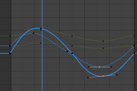
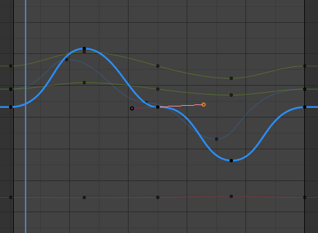
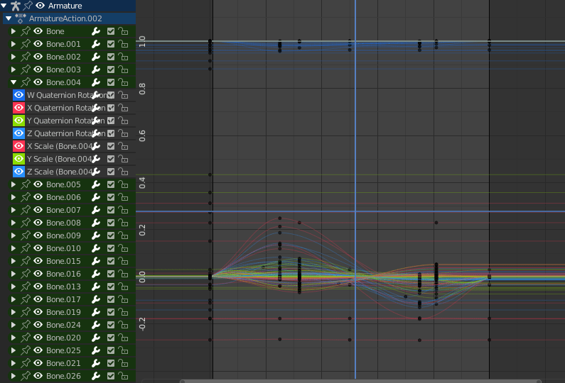
Hip motion curves below. The line represents the z Quaternion rotation. As you can see I have adjusted some of the angles on the curves to create a smoother interpolation. especially on the beginning and end of the animation.
original default curves.
Original Un-smooth animation. Only hip movements are bad.
New Curves
Smoothed animation. (Showing only hip movement changes. )
I smoothed the rest the curves similarly. but won’t show as much detail on each one because there is a LOT of them.
All curves screenshot.
This is the final result when imported into Unity.
In order to fully play test the Level we wanted to implement the dialogue system so the player can be guided around the level as they will be in game.
To control the dialogue systems we came up with the idea to use an overarching level controller game object to hold scripts which control which XML file is pulled when the Character dialogue script (created by Megan) retrieves the XML data. The only change I have made to the character dialogue script itself is to change the string containing the XML path, to a list containing multiple paths. The index of this list is then determined by the Controller script.
The work is done here.
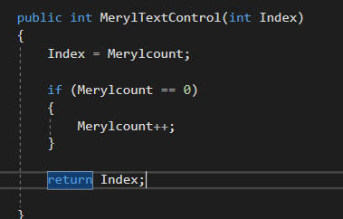
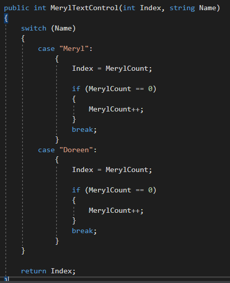
This function is called from the character dialogue controller script. It Checks if the player has already talked to Meryl. In future I will probably change this so it works in a generic way with all characters, possibly by passing in a character variable which changes the functions behavior.
A few hours later and I have done as I thought I would, and passed a character name alongside the Index
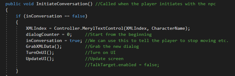
There are then some changes to the CharacterDialogue script.
The XML path is changed to a list, which is setup in the inspector to contain multiple paths.
An index used to access the list is determined when the player starts an interaction by our controller script explained above.
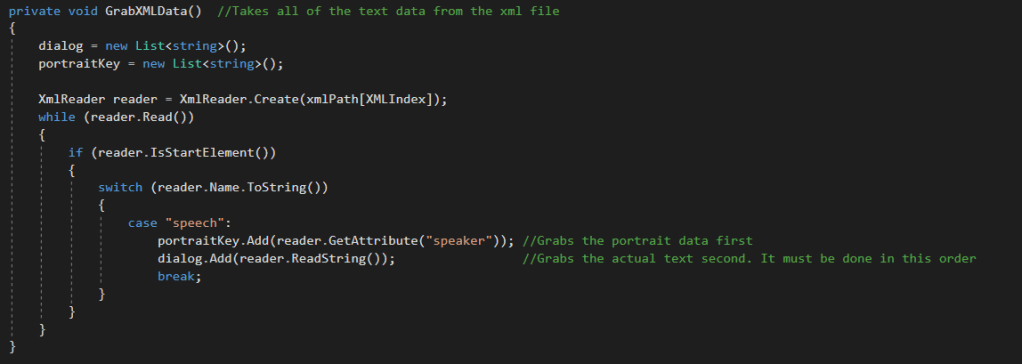
The GrabXMLData() subroutine has been slightly edited to get the string at the index we provide using the XMLIndex variable.
Next was to get the Quest Popup to appear. As shown in Shannon’s blog in the below image.
The Idea I had for implementation was to adapt parts of the CharcterDialog script to detect if this character would be giving a quest. If this was true then when we finish a conversation we also check to see if we need to start the quest popup. The popup itself will be controlled by a function in the Controller Script as later on when the character picks up quest items the controller script can handle this and change UI based on the beans.
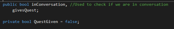
First I add some variables to control the behavior.
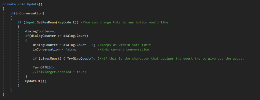
Then on the part of the script than runs when a conversation is over we check if the character is giving a quest.
And here at the end of the script is a new subroutine that checks we haven’t already given the quest. If not we use a function from the controller script to turn the quest popup on.
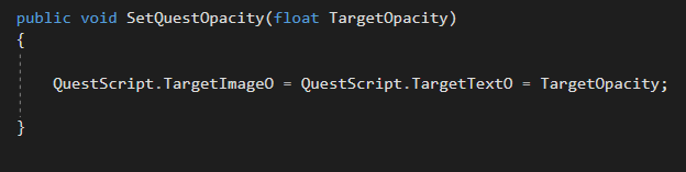
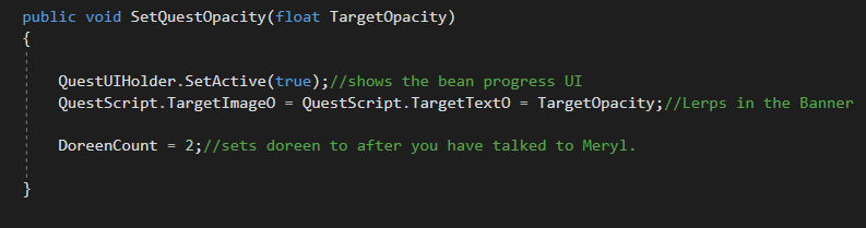
below is said subroutine, As you can see it simply updates the target opacity for the text and banner.
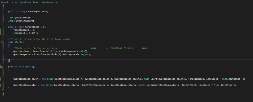
And below you can see how the opacity target is being continually Lerpt too in the quests control script.
Quest Control Script
This is a rushed job (You may have noticed the code is not as organised as some of my other work.) But We have very limited time until the deadline now so getting all the functionality of the game finished is more important than clean code right now.
We also won’t really be punished for it as most of the problems would arise from wanting to reuse this code in future scenes. However We are only developing a virtual slice.
This is the result of the quest popup.
Next I had to get the Bean Icons showing, and write code so the quest could be completed.
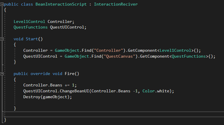
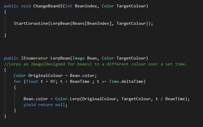
While researching into efficient ways to change the colour of the bean icons. I Realized how much more powerful Coroutine’s are. This enabled me to design the beans colour system very nicely. by creating a simple colour Lerp over time coroutine, and calling it when a bean is picked up by writing a n overridden interaction receiver script for the beans to use as their interaction script. .
I am embarrassed by my use of the syntax GameObject.Find() as it is very dangerous and can cause a lot of errors if people who do not understand the scripts try to change things. But like discussed before I was running out of time.
This is the function(s) that are called form the UI control script.
Could not find a way to call a coroutine even when public. So resorted to writing a public function to call it.
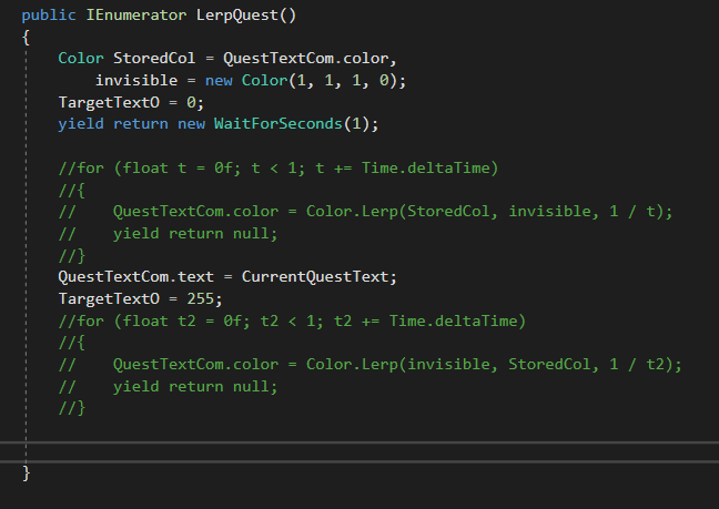
I was originally going to implement my new coroutine knowledge for the quest text transition once you have picked up all the beans. But I realized that this method conflicted with my original implementation. So rather than re-writing the original implementation I just used the old method of changing a target opacity, which is being Lerpt towards to every frame.
Showing how I thought i was going to implement the quest text change then and how I did.
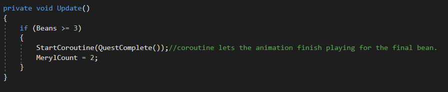
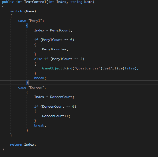
The final thing to change was some minor dialogue updates and then finally to turn off the quest UI once the player talks to Meryl for the final time.
Getting Meryl to say the correct thing once you have all the beans.
This functions controlling the quest setup runs after talking to Meryl for the first time so allows us put put Doreen on her final piece of dialogue.
We turn off the Quest finally with this if statement stored in the function the dialogue controller runs when fetching the XML Index.
A final re-iteration that I understand all these implementations make for horribly un-reusable code. Indeed If I have time I will re-design a lot of this architecture to allow for future re-usability. But for now I didn’t know I would have to write this code, and We need it done fast, so here it is!
This is the final result. Not sure why the text transition is not smooth. But we can fix this graphics bug after play-testing.
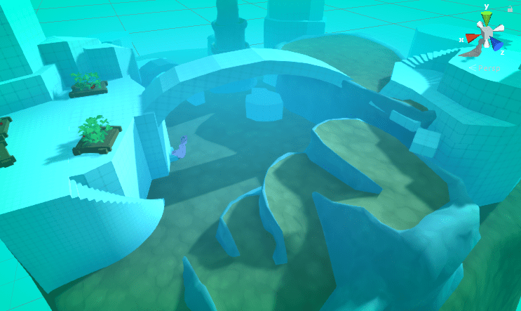
As the method for creating our environment assets meant these assets were hard to change retrospective to future testing. I suggested to Team lead that before environmental modelling was conducted we should play test the grey box level first.
As everyone else was busy I got to work on preparing a new scene for play testing. I exported a lot of the game objects we had configured in our demo scene to prefabs, this enable us to immediately implement them into our new scene.
Default directional LightingNew scene with the directional lighting and Post-Processing configured.
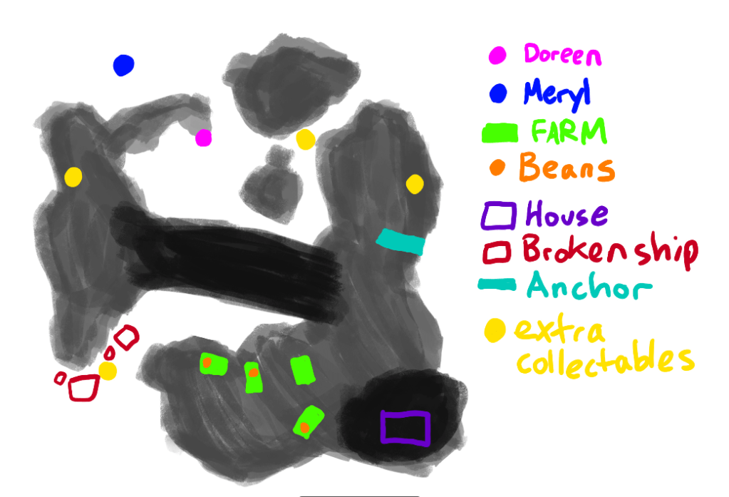
Megan gave me the level designs she had in mind over slack so I could configure the level as she intended it when doing the grey-box.
Megan’s level design element placement
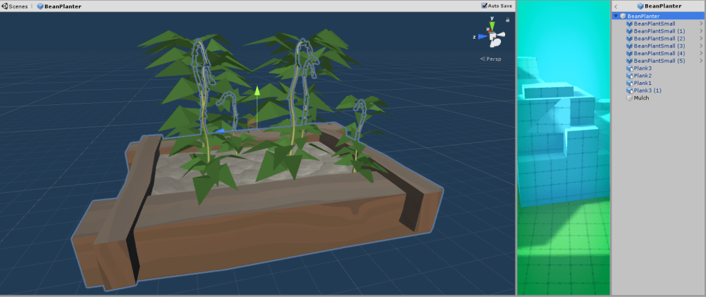
I also started grouping smaller assets into groups and saving these as prefabs. An example is shown below with the bean planter assets actually being a combination of several other assets. Namely the planks, and bean plants.
The Components can be seen to the right in the inspector.
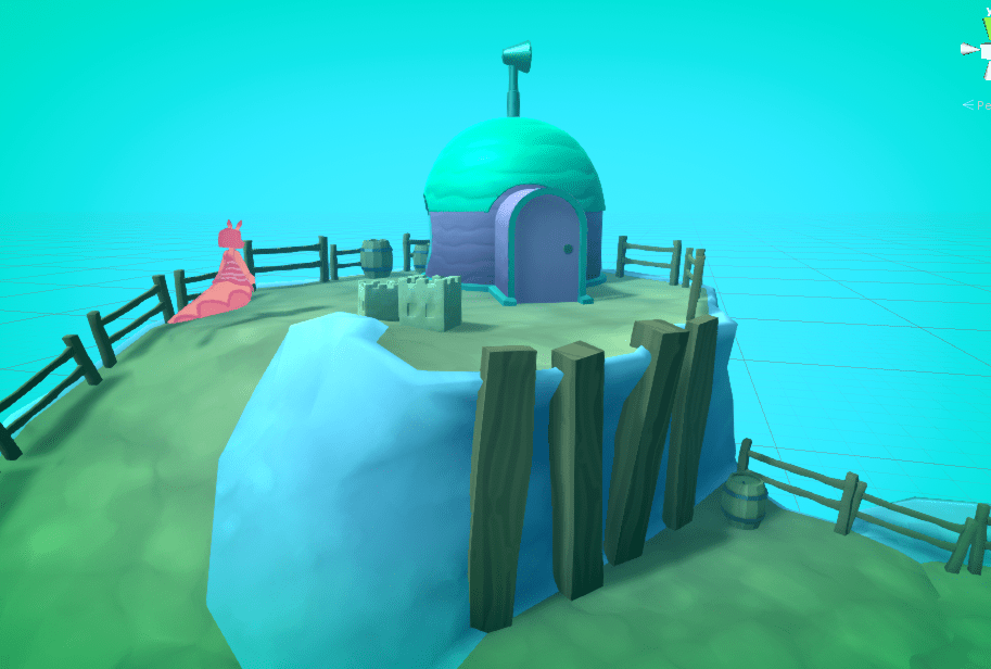
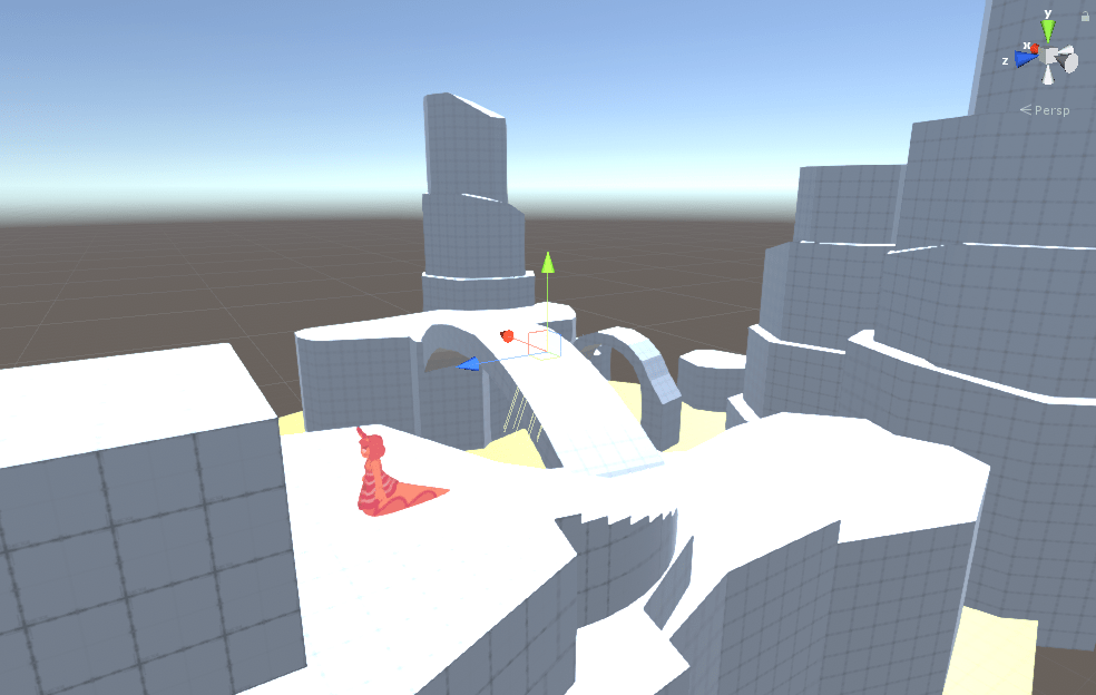
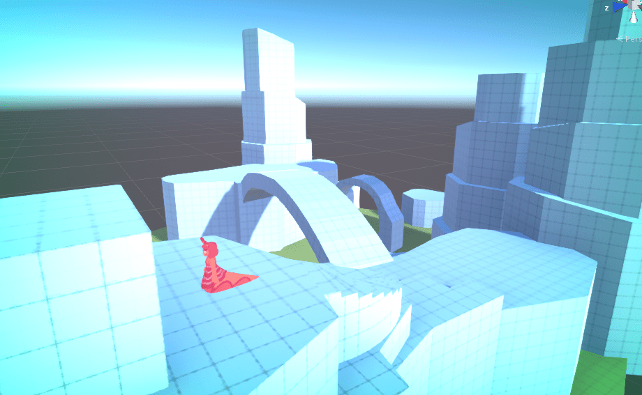
I imported Megan’s Grey-box and then positioned the characters And planters according to her diagram.
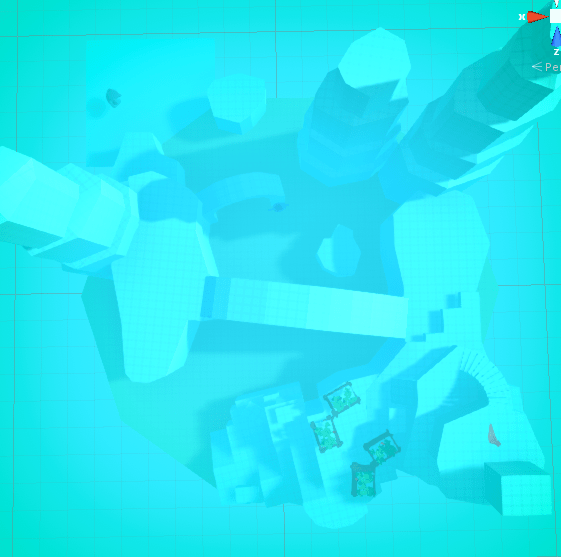
The Unity Scene From above.
I also setup the dialogue so you can have the basic interaction with Meryl. But will need Megan’s help to setup the actual test dialogue if we decide it is needed for this play-test.
Initial Opinions.
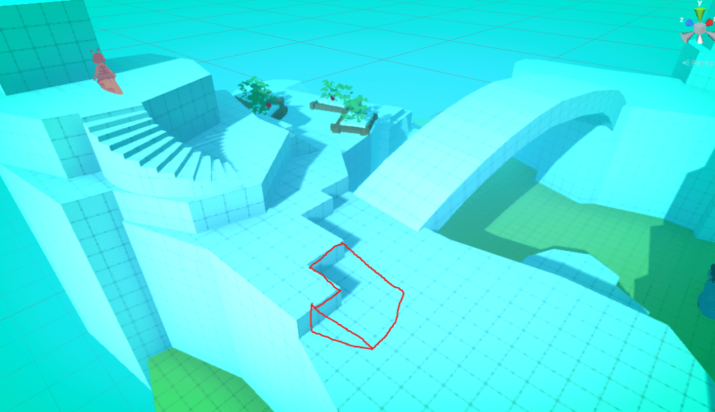
There needs to be a ramp from the edge of the house to the drop-down, and back up again. As It is intuitive for the player to drop down to the lower level. If they do they are then stuck there.
Suggested Ramp location.
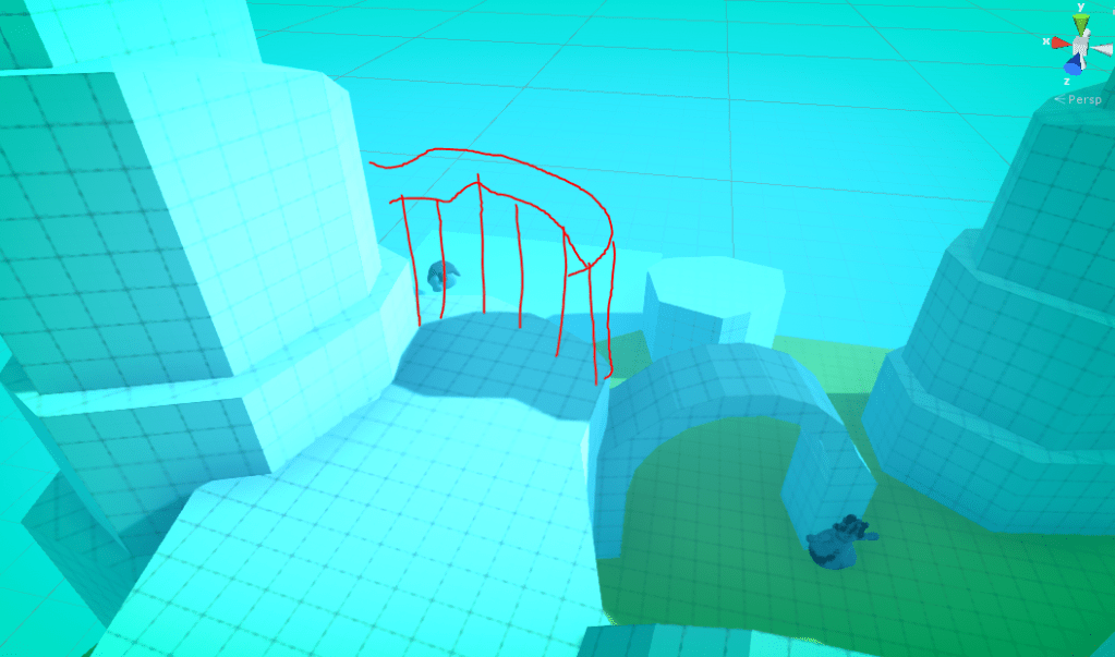
The second note was that Meryl can be seen from the edge of the platform which player can easily walk through. I think it would be beneficial to drive the player to the Anemone before meeting Meryl.
Suggested Geometry implementation.
When Thinking of this idea it could be fun to even implement a window in this “wall” to allow players a peek or Meryl as a reward for exploring across the bridge, while still forcing them to follow the rout we want them to take.
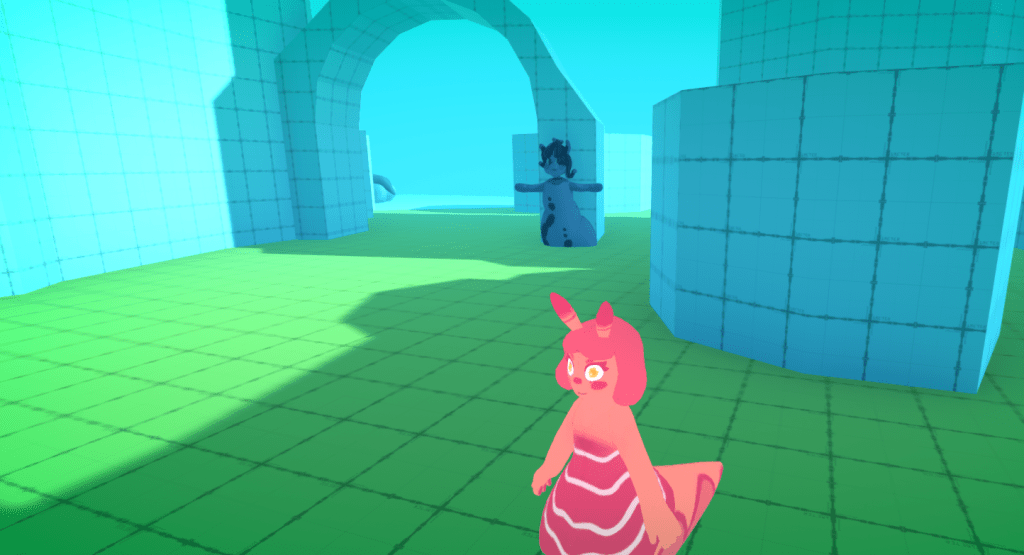
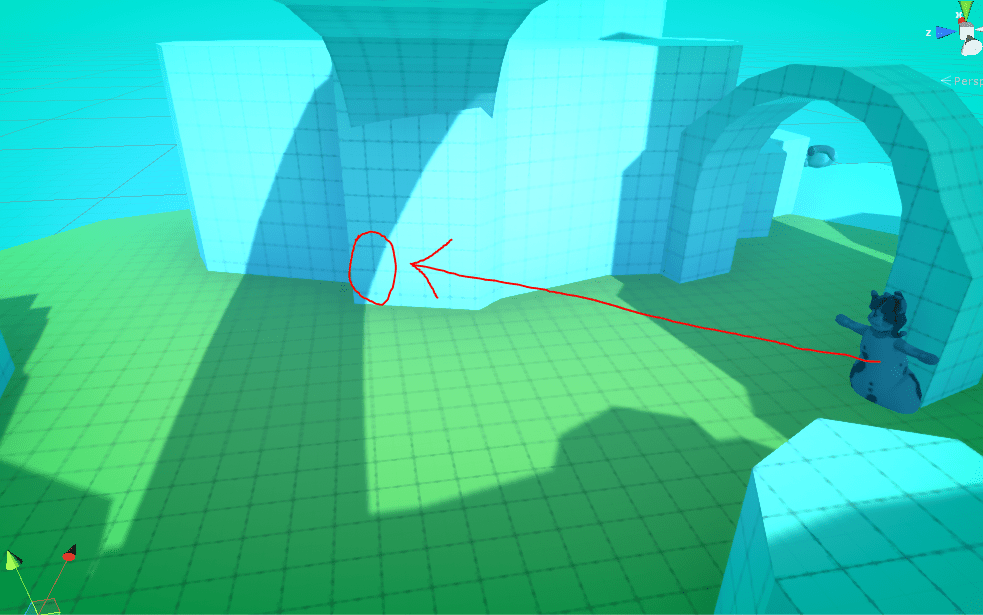
The final thought is that we should move the Anemone character further forward, as by the time you can see her you can also blatantly see Meryl. It makes the level very linear. I would suggest moving her to the base of the cliff under the bridge.
Current position. Proposed position.
This Blog Will be shared with my teammates, and a separate post will be created documenting the changes we make as well as further testing results.
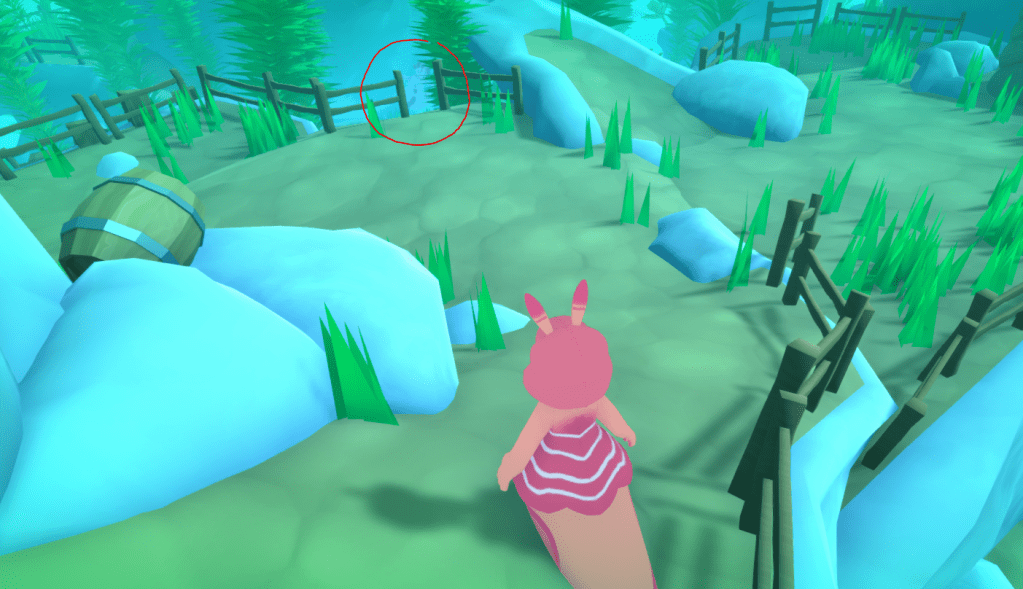
I also think It would be beneficial to move the beans so they are further spread out across the map. or at least not right at the beginning as currently If players do not pick them up they have to go back to the beginning of the map, which isn’t really that fun.
This is a “follow up” post to my first post about shader development. In this one I explain the in’s and outs of the leaf shader development. I will be building on the understanding of shaders I talk about in my first post, so it’s a good idea to read that first.
The first key bit of information to communicate is that I will be using a geometry shader for these leaves. A geometry shader adds another step between the vertex and fragment shader. meaning the pipeline becomes.
Vertex -> Geometry -> Fragment.
In the geometry sub-shader we are still working with within vertex space, a geometry shader allows us to redefine where the vertices are in the model we are shading. This means we can add or remove vertices to our geometry. Depending on what we choose to define in this sub-shader, you can create pretty much any geometry imaginable. This geometry is then passed to the fragment shader ready to be drawn to the screen. Its important however to realize that the geometry we create can really only be used for aesthetic purposes.
This being understood let me explain the theory behind this shader.
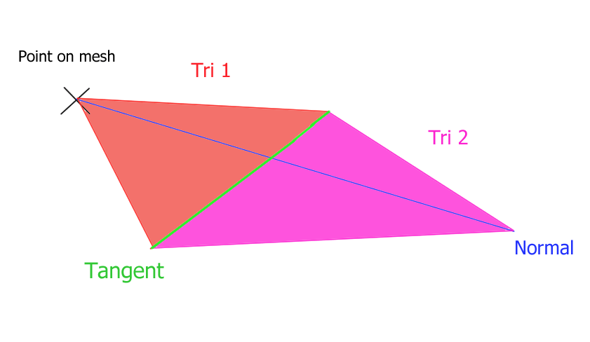
The basic premise was that I could use a geometry shader to render leaves instead of triangles or vertices, by adding two triangles extruding out along a normal.
Shader concept Diagram
The next thing to think about was how I was going to get all the information I needed. As you can see the main two vectors I needed for the leaf is a normal facing away from the geometry, and a tangent vector to that normal along the y axis.
Each vertex has a normal so getting that is easy.
The hard part was finding a way to get the tangent. In the end I decided to use individual triangle vertex positions to calculate it. The alternative would be to calculate a transform using some sort of Quaternion rotation, which would require constructing a rotation matrix within the shader itself. (Which I looked into, but decided wasn’t necessary for this project)
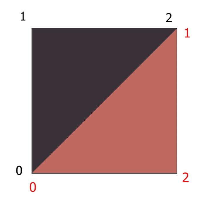
Even using vertex positions presents some problems, due to the way Unity labels vertices in geometry.
Unity’s triangle vertex labeling convention.
As you can see illustrated in the above diagram Unity’s convention is to label vertices on a triangle in ascending order, with the numbers increasing in a clockwise fashion when viewing the triangle from a position where it’s normal is pointing towards to camera.
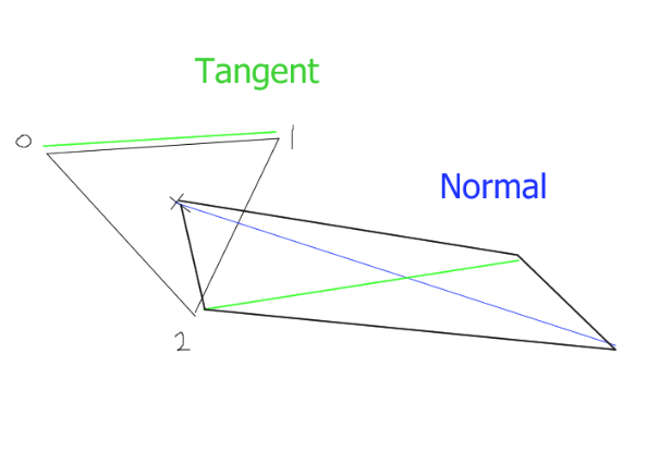
This means that while getting the vector between point 1 and 2 on one triangle gives us the tangent we want. On another it gives us a vertical tangent instead. I spent an evening trying to solve this problem by adding and taking away a combination of these vectors, but to no avail. I ended up just getting results like that shown below.
Bad Leaf Shader
So instead I opted to not use a quads in my mesh for the leaves, and instead place a triangle in the correct orientation wherever I want a leaf. This means that each triangle will have the same tangent if I simply use (0->1) and orient the triangles so that this vector is a tangent to the vertical axis.
Implemented I was able to create a simple leaf shader.
Much better!
The next stage was to add some animation. The GPU is bad to doing complex logic, so if you want a lot of “random values” for something like a wind animation it’s a good idea to sample a texture. You add the values you get from your sample to the positions of your vertices and then multiply the texture coordinated by time (which gets the time since the shader started running. ) Then kachow, you have got animation. (Show below)
Pretty wind leaves!
Now you may notice that this shader is still not reacting to the lighting in the scene. This was the final hurdle for me to cross before the shader was game ready.
Essentially Unity handles most of this for you, and you just have to know the correct syntax to setup lighting. which I will explain more when walking through the actual shader code. Most of the work was just hours of me reading through Unity’s limited shader examples here as well as there #include libraries for lighting. Which are hosted on Github.
So, now that you have read through that. let me break it down for you a little.
Starting with the properties. These are just shaderlab syntax properties, these show up in the inspector when interacting with a material using this shader. they allow user input.
The top line defines where in the shader list (when selecting a shader to use from a material) this shader is stored.
Ct the start of the next block we import two CGinclude libraries. One is for basic surface shader stuff. The other contains a load of lighting stuff we need, mainly shadow functions and datatypes.
Here I define my structs appdata is passed to the vertex sub-shader, and v2g is passed form the vertex to the geometry sub-shader. (you may notice that these structs are identical and yes we could use the same one for a minor optimization. But this shader was adapted form harry’s grass shader and this is how he left them, and to be honest I forgot about this until writing this post. )
The semantics used in the structures are pretty self explanatory. NORMAL is the verts normal, POSITION is position, and TEXCOORDX is a texture. when using TEXCOORD you update the number on the end to change which map slot is used. Each texture can have 6 seperate maps (don’t quote me on that read the HLSL documentation linked last post)
The g2f struct, you guessed it passes data form the geometry to the fragment sub-shader. here we grab a few extra things such as shadow coordinates, the view direction and we also pass some fog data in the 2nd map slot. (Fog takes up one of your 6 texture slots)
The unityShadowCoord4 type is defined two layers deep in the ‘Autolight.cginc’ and then another CGinclude inside that file.
At first glance this may look like the geometry shader, do not be fooled! This is just a helper function for the actual geometry function which is below. All this code has to be run for each vertex we want to add, so it makes sense to put in in a function to speed things up.
Next is our actual geometry shader. This is where the bulk of the work for this shader is done.
Working through it we start with a max vertex count, which we update to set how many vertices we want to create for each triangle(or whatever we choose to take as input for the geometry shader).
next is the geometry shader decleration. Unlike other subshaders it does not return a struct, But instead pushes any triangles made the Triangle stream. This shader is setup to take triangles as an input. But if we changed the initial parameters to ‘vertex v2g IN[1]’ we would instead run this shader for each vertex. Which can be useful to understand for future shaders.
onto the first line of the shader, we instantiate a new g2f struct, ready to be incrimented to the triangle stream.
Next we calculate some random numbers we need using our function we declared earlier.
Next we do a load of math to find all the different vectors and numbers we need.
We calculate the center (barycenter) of each triangle. And then calculate the normal ina similar fashion (Adding everything together and dividing by 3).
We multiply the normal by the random value to allow the designer some random leaf length controls. Then we add the leaf angle to the normal y value to allow us to control the angle of the leaves in the inspector.
We calculate the tangent as I discussed above by finding the vector between the two points. We then set the y values to allow for a hacked leaf rotation functionality. We add all our random variables together instead of generating a new one for efficiency, and because the rotation random here doesn’t matter too much.
Next we sample the texture values for the wind texture, based on our barycenter’s world location. We store this in wind for later. By using _Time.y (another inbuilt variable) in our offset we can scroll the texture as time passes and thus create the animation for the wind.
We get the curve increment and save that for later, this values is later added to the center of our leaf to make it curve downwards or upwards.
We do a large vector calculation using the cross function from CG to find the normal for our new faces. and then we run our helper g2f functions 6 times with the parameters to create the vertexes for the two triangles we want to make.
Ourur first vertex is simply at our barycenter coordinate.
Our second third fourth and fifth. Simpy add + or – the tangent and + the normal to their position, and then times this by length to allow us to adjust the leaf length in the inspector. We add one lot of wind to these leaves.
The final point we calculate by adding 2.5 * the length to it’s normal meaning the thickest part of the leaf will be about 2/5th’s along its length, and then add a curve increment + our wind times 2. This makes the leaves curl up or down, and makes the tip of the leaf blow more in the wind than the rest.
This is the lighting pass, and does most of the work we want. We turn of culling to render the backfaces of the leaves so they aren’t invisible from below . Using #pragma we define all the different sub-shaders we want to use for this pass, and we pass in our sub-shaders from above. We also pass some fog information which just makes the fog work, unity handles all the fog stuff for us.
The CGinclude ‘Lighting’ use referenced to get us the shadow functions/data we need.
Next is our fragment shader definition. This is defined here because we have a different fragment shader in our next pass.
I have used the VFACE semantic in this shader to allow better backface lighting. What VFACE does is return a value between -1 and 1 depending on which was the face is facing in relation to the camera. -1 facing away, 1 facing towards the camera.
A breakdown of what the sub-shader does follows.
Samples the colour of the texture on the pixel we are currently shading. Stores this in col.
to prepare before the lighting is added to the raw colour, we flip the normal of the face is the face is facing away from the camera (This corrects the lighting on back faces)
We then get the scene lighting for that pixel using inbuilt functions from the Lighting.cginc.
We grab the shadow by passing our unityShadowCoord4 we defined in our geomerty shader helper function. into the inbuilt shadow function (SHADOW_ATTENUATION) provided by our cginc files. This gets us how shaded the current pixel is.
Finally we times the colour by our lighting and shadow, and the scene ambient lighting fetched by ShadeSH9().
And apply fog.
The pixel colour is now correct and is returned with return col;
Pass
			{

				Tags {"RenderType" = "Opaque" "LightMode" = "ForwardBase"}
				Cull Off
				CGPROGRAM
				#pragma vertex vert
				#pragma geometry geom
				#pragma fragment frag
				// make fog work
				#pragma multi_compile_fog
				#pragma multi_compile_fwdbase
				//#pragma shader_feature IS_LIT

				#include "Lighting.cginc"

				fixed4 frag(g2f i,  fixed facing : VFACE) : SV_Target
				{
				// sample the texture
				fixed4 col = tex2D(_MainTex, i.uv) * i.color;
				i.normal *= facing < 0 ? -1 : 1;
				float light = saturate(dot(normalize(_WorldSpaceLightPos0), i.normal)) * 0.5 + 0.5;
				float shadow = SHADOW_ATTENUATION(i);

				//shadow = facing < 0 ? light : shadow;
				col *= light * shadow + float4(ShadeSH9(float4(i.normal, 1)), 1);
				// apply fog
				UNITY_APPLY_FOG(i.fogCoord, col);
				return col;
			}
The final pass is just for casting shadows. This is all powered by the one function SHADOW_CASTER_FRAGMENT() in our new fragment sub-shader named fragShadow. You can see we define this as our fragment shader in this pass’s #pragma.
We also have to setup a tag to tell Shaderlab we want to render shadows.
Wonderfull! all done. I hope this helped you understand a bit of what is going on in this shader. I tried to explain it all clearly but to be honest shaders are hard, and there is a lack of good resources about them. Maybe this post can help some people in future.
I will leave you with a giff of the shader working in Unity.