Shader Development.

This is going to be a long post about all things shader. I have been developing two main shaders for this project.

The Grass shader which I just added fog functionality too (The rest is just Harry’s grass shader source: https://halisavakis.com/my-take-on-shaders-grass-shader-part-ii/)

The second shader while inspired by Harry’s is actually built by your’s truly and I will thus take credit for it’s creation. As well as all the problems It has.

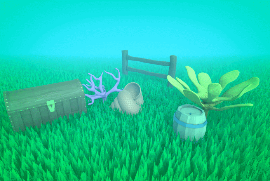
The Idea behind the grass shader was simply that I could create a shader that instead of making grass blades, rendered leaves. This would then allow me to add some leaves with wind interaction(Or water currents in our case) It would also be a lot more efficient than Actually importing leaves as geometry into the scene and then just using shaders for animation (which is what most games do).

I am going to try and go over everything I know about shaders here. As my understanding is much better than in my last post. I didn’t think That I would finish this shader in time for it to be included in the project which is why there isn’t more documentation up until this point.

Most standard surface shaders use two main sub-shaders to do most of the work and achieve the effect they want.

  • The Vertex shader. Which collects and can edit locations of vertices.
  • And the Fragment shader. Which works using pixels and handles actually displaying our geometry to the screen. Here is where colour effects are handled.

The majority of the Shader is written in CG/HLSL, most of the documentation for which can be found

here: http://developer.download.nvidia.com/cg/index_stdlib.html

and here: https://docs.microsoft.com/en-us/windows/win32/direct3dhlsl/dx-graphics-hlsl

Stuff that isn’t CG is written in a syntax labelled as ShaderLab by Unity Documentation here: https://docs.unity3d.com/Manual/SL-Shader.html

The structure of most shader code is as follows.

Properties

{

Values defined for each material using the shader, allows the shader to be customization.

}

SubShader

{

CGINCLUDE (Specifies the beginning of the CG/HLSL code)

#include files. These are libraries for shaders, they usually contain Unity specific functions to use. You can write you own as well which allows multiple shaders to any helpful functions that you make

Structures. These are used to pass data between sub-shaders. They use HLSL semantics to identify what data you intend to pass to each parameter. Documentation for semantics: https://docs.microsoft.com/en-us/windows/win32/direct3dhlsl/dx-graphics-hlsl-semantics?redirectedfrom=MSDN

Property redefinition. As we are now working inside CG we have to re declare all our properties as their specific variable type in CG.

Shader specific Functions, we can write functions the same way that we do in C#. CG is basically C# you can read more and about that on the official CG documentation.

here: http://developer.download.nvidia.com/cg/Cg_language.html.

Sub-shaders, this is where we put our sub-shaders and where all the work gets done. Often the sub-shaders in CGinclude can be used, in which case you may find shaders missing certain sub-shaders from this section as they are instead defined in CGinclude.

ENDCG (end of our CG/HLSL code)

}

Pass (surface shaders in Unity use passes, the less passes the more efficient the shader)

{

Tags{‘tag’} tags in Shaderlab are used to communicate the intent of the pass to Unity’s rendering Engine. We can also communicate other non tag information here such as ‘CULL OFF’ which tells unity to render back faces.

CGPROGRAM

#pragma. The ‘#pragma’ syntax is used to define which sub-shader to use in this pass. We simply pass the name of the corresponding sub-shader we want to use. These can be form CGinclude or any other library or from our above code.

We can include any pass specific sub-shaders or function here if we want.

ENDCG

More Passes/Fallbacks. At the end of the shader we can define more passes as done in the pass above, or we can specify fallback shader configuration for Unity to default to if a users hardware does not support our current shader. You will often see the standard Unity Diffuse shader being used as a fallback.

}

Now you understand the basics of shaders in general I can explain to you in the next post the ins and outs of the grass shader I developed.

Environment asset workflow

Our team was struggling to come up with a way to create the assets we wanted for our large environment pieces.

The problem we had was we didn’t want to bake textures to large environment pieces the same way we have been baking the smaller assets as these files would have to be huge in order to retain a non blurry texture.

To fix this I looked at how some other games dealt with this problem. Starting with dying light.

Form my analysis I concluded that Dying light uses like many games a editable flat terrain layer type 3d object, which can be procedurally textured and edited from the game engine. Unity has a similar system however it doesn’t handle vertical texturing very well and stretches textures very badly. This can be overcome by masking the stretch with other objects, but then why not just model the entire things with individual objects.

These edited screenshots highlight the props not part of the ground plane, hopefully making my explanation clearer. and the ground plane easier to see.

With my second game Dark souls 3 . It took me a while out figure out what was going on. Bit in the end I figures that a universal ground texture was being applied to the ground, and then layer with lots of extra 3D objects to hide the tiling.

Again Edited screenshots highlighting the ground plane and the object individually, This time the ground plane itself is in yellow.

The implementation of the textures in dark souls gave me an idea for how to implement textures in our project in a way that wouldn’t involve baking any maps for our larger pieces.

As long as you are using Unity to map your textures, pixel space doesn’t matter as Unity skips allows you to skip the baking process for any maps, and apply textures directly instead. This means you project is a lot smaller, but does mean that you have to ensure all your 3D models are to scale. It also stops you from masking any seams, other than by hiding them with geometry, which is what I plan to do. I made a few iterations of experiments and I will document these below.

Checking that geometry made to scale always uses the same scale of material.

Next I made a prototype asset and populated it with some add-ons, like dark souls does, to make it look more natural.

I thought the textures were too standard. After getting feedback from my team they agreed, and I made a new texture for the environment that learnt a lot better.

The only problem with this is that it shows the seams of the materials, as unity does not have any inbuilt forms of seam masking.

Seam is visible.

We are going to move forward with this form of environment design. With the following workflow.

Model an environment piece with a blender file saved within the project. Allowing for real-time scale checks while modelling.

Create textures, scaled to look good, apply these to each asset.

Export Finished models as an FBX, and move the blender file to a backup location when your ready to build.

Style Guide

Going Home Style Guide

Contents

Asset Naming/Filetypes: 2

Universal Rules: 2

Folders: 2

Code: 2

Art Assets: 2

Textures: 3

File Structure: 4

Assets: 4

Scripts: 4

Models: 4

Notes: 4

Notes before starting to read.

Examples will be contained inside apostrophes to clearly denote what is being referred to.

Example: ‘This is an example’

Asset Naming

Universal:

– No_spaces_ever, If you feel the need to use a space use underscores ‘_’

– When in doubt use Pascal Case, Written by capitalising the first letter of each word in a name, and not using any spaces.

Pascal case example: ‘PascalCase’

Folders:

– Try to contain one file type (or very similar filetype) per folder.

Group files on context.

Example: USE ‘Textures/PineTreeTall/Materials’ DO NOT USE ‘Textures/Materials/PineTreeTall’

– Be descriptive and specific.

Example: USE ‘PineTreeTall’ DO NOT USE ‘Tree03’

Code:

– Use pascal case for public Variables.

– Use specific variable names

Example: USE ‘RotationSpeed’ DO NOT USE ‘Speed2’ OR ‘Rspeed’

Art Assets:

Models

– Use FBX File type. (Compatible with substance, and is smaller for the build.)

– Use description to differentiate between assets. Use the asset type before the description. While this isn’t correct English it’s more useful when searching.

Example: USE ‘PineTreeTall’ DO NOT USE ‘TallPineTree’

Textures:

– We are using the Metallic Roughness Unity Standard Shader.

– Use an additive suffix, meaning if a map has two different sets of information in it add both suffixes to the end of the filename.

Example: Use ‘TallPineTree_MT_S’ to denote a Metallic and Smoothness map.

Suffix List:

_AL : Albedo

_S : Smoothness

_MT : Metallic

_AO : Ambient Occlusion

_H : Height

_N : Normal

_EM : Emission

_DM : Detail Mask

File Structure

These structures are just abase to be expanded upon.

Root

+—Assets

+—Build

\— Tools – If we decide to use any Unity add-ons etc.

Assets

+—Art

| +—Models

| +—Sound

| +—UI

| +—Materials

+—Code

| +—Shaders

| +—Core – Contains key scripts or parent scripts.

+—Prefabs

| +—Environment

| +—NPC

| +—Player – Contains camera as well as the player

+—Resources

| +—XML*- Dialogue files, not sure of the name.

+—Scenes

Materials

+—Environment

+—Character

Core

+—Environment

+—Player

+—NPC

+—Tools – pickups etc.

Notes:

If you think this list needs expanding to include more style definition let the team know, don’t just make up standards!

Unity Collab Initiation

This post will document some of my initial work with Unity collab, and how we collated assets/tested the collab system.

Initially Megan setup the collab, Once we were all added and had tested initial commits worked as expected. I set about making a style guide for the project as we didn’t have one yet. This document is obviously evolving as the project progresses, but it’s current state can be seen it my Style Guide Post.

Afterwards I set about adding all my assets I have been working on to the project, and pushing them in commits. Setting up the post processing and lighting to achieve an underwater look.

Assets Setup In Unity

Later on when working together with other members we experimented with how commits effect one another, and the local changes to ensure future changes were handled smoothly.

We realized that Not only would local changes from your asset folder remain intact when you updated the project to a newer push, But local changes such as an additional object in a scene remained even when that scene was updated in the most recent version.

Megan implemented the grey box, and I added this to the demo scene and toned down some of the post processing, so the players sight was longer. I also turned up the shadow distance, and changed the step limit of the player controller, to allow the player to interact with the grey box correctly.

Grey box test screenshots.
Grey box test screenshot

Texturing The Anemone

Texturing of the character was done using substance painter. I Used a base layer to setup the basic parameters I wanted for the material, and then painted alterations on-top. Additional colours were added by creating a flat layer of colour, and painting in a mask. This workflow allows for easy colour alterations later on with ought re-painting.

Base Layer with one colour.
Layer Mask

I used the high poly mesh I created to bake normal’s for the low poly model, giving the mesh a smooth detailed look. And then painted on some normal information around the neck, to give the illusion of some more height details.

Normal Map

With several more layers. This was the final result. Ready to be imported Into Unity.

Final Textures

Modelling The Anemone

I started with simple Poly modelling for the main body, to create a high quality low poly mesh for use in the game.

I used a new object (an Icosphere) and then duplication of these to create the tentacle hair. Once complete I joined the hair together to create one object.

Low Poly

With the Low poly mesh complete. I used the subdivision surface to create a high topology mesh, and then sculpted in the neck decoration that I wanted to show using a normal map.

High poly

Detailed texture Creation.

This is going to be an in depth look at the methods I use to create my textures. Specifically the brain coral Texture. (Shown below)

Brain Coral texture.

The methodology for most texture I create is to start with height information, once you have a strong height map you can use this to inform your colour and roughness/metallic designs.

However when doing simplistic stylized textures like the ones for this project, Its often simpler to start with the shapes you want to create, and not necessarily assign said shapes to the height properties of the texture (as the textures are so flat). However for this texture the shapes are defined using height initially, and thus it’s a good demonstration of my general texturing workflow.

As mentioned the first thing to do is to define the height map. When doing this it is good practice to define the large shapes first, followed by the smaller shapes. (I am mentioning this to show understanding, even though this texture will only have large shapes)

To define the shapes we want we can use the Reaction Diffusion Node. Which will create lines following gradients on another texture. turning this Plasma Texture.

Plasma

Into this flat black and white texture.

Reaction Diffusion.
Designer Nodes.

All this looks like we have created the shapes we want already, but plug this texture into the height and normal maps for the texture and you will see the shapes look very artificial and rigid.

Hight is too flat.

To fix this we can plug in a bevel, with a custom curve (defined in designer by using a gradient with levels applied for more control. )

Designer Bevel setup.

the result of which (after some experimentation) turns this.

No Bevel.

Into this!

Bevel!

The effects of which really show in the 3d View.

Much More Natural! (3D View)

The next thing to do is to assign some colour, I knew from referencing that most coral of this type was yellow, so I went for a yellow colour. This is also the stage where I turn the roughness up to fully white, and the metallic to 0 (fully black). So reflections wouldn’t mess with my coloring, Also coral is basically completely rough anyway, so this will probably remain this way.

From the coral textures I had created before I knew a good way to create colour maps, was to merge two perlin noise textures with gradient maps applied to them for hue variation together. So I went ahead and created two of these textures with different random seeds so they looked different, and then also warped them slightly using Dete’s directional warp (Which is a utility node created by Daniel Thiger https://www.artstation.com/dete All it does is apply warps in 4 directions instead of having to hook up 4 individual warps to achieve that effect, which saves lots of time). The warping makes the colours follow the height of the texture making it look a lot more natural.

Perlin Noise.
Warped Perlin Noise
Node Structure
Final Colour Map.
Texture so far.

As you can see the texture looks ok. But its a little too flat for my liking at the moment (Although We may have to turn a more dynamic texture down later for cohesion with other textures.) Its easier to tone down textures than to retrospectively make them more detailed. So I want to add another layer of information, something that further accentuates the height. Many rocks/coral have white patches where high parts have been damaged, so I want to add a light layer to add this effect. This is done by using a linear dodge blend node using the height map as the mask for where to apply the effect. First we edit the height using a levels node, as I actually want a slight bit of white applied to the whole texture for later colour grading.

Leveled Height map.

then we blender a flat white colour node, with our current colour map, using this new height map as our opacity.

Final Colour Map.
Node setup showing leveled height-map and the blend.

And that’s a wrap. I chose to leave the Roughness and metallic maps as they were. As the texture looked good already.

Final designer graph shown below.

UI Development

I was drafted to do the UI to cover some people who had fallen behind. After looking at a the button setup for a little while in Unity I figured we can have a universal button script, and then have the buttons themselves call the public functions to allow interactivity (All contained in one script)

Inspector showing the assignment of the ExitGame() function from the script ButtonController, attached to the game object MainMenuCanvas.

The script is as shown below. Its pretty short so I will just post the whole thing.

As mentioned before the public functions are the main aspect of this script. We have functions to load scenes (the scene determined by public strings in case of name changes) and we have another function that enables and disables the canvas, this function is also called in Update() when the player presses escape, which allows the player to operate the pause menu using this key as well. The key can be easily rebound in the script for UI updates later.

Lovely Demo Menu

The pink overlay (as mentioned in Shannon’s GDD) is created by a square stretched across the entire screen, with a low opacity.

Giff showing menu interaction.

The exit buttons will only work once the application is built.

Interaction Script

This is a simple script that allows the player to interact with object in the environment such as pickups.

Essentially we have a trigger sphere around our player, when an object is inside this sphere if we hit e, or in this demo’s case the mouse button (Axis can be configured from player settings) we want to do … something to that object. These scripts are written so later on they can be changed, to accommodate more behaviors hence the use of the case statement.

The interaction happens locally within the script attached to the object you collide with “Fire()” is used to start the behavior. Again this is for future proofing when we add more complex behaviors.

As you can see currently the interactions are very simple. but will be expanded later.

Player picking up the item.

Programming camera And Movement

Making this guy walk around.

This is the document where I explain how the camera and movement/rotation code works.

Demo

Camera Code.

The bulk of the work is done in two functions. HandleMouseInput(), and HandlePosition().

Essentially we want to create a Dark souls style third person controller. So we want the camera to orbit the player relative to the mouse input. First thing to do is to get the players mouse input.

We times the inputs by a sensitivity to allow the player to customize their control speeds. As we don’t want our camera to reach a 90 degree angle from the player (as this can cause control issues with repetitive flipping/ rotations ). We clamp the Y input.

The handle position function controls the actual location of the camera. We calculate the cameras locations by creating a vector the length of the distance we want from the player and the camera. We then create a rotation determined by the current x and y of the camera. Our final position for the camera is the center point of the player model plus the vector created by multiplying the vector of length that we created by the rotation towards our mouse position. If the y value of this vector is below a value we set for the floor, then we simply set the y to that value, this stops the camera clipping the floor. We then set the position of the camera to this position, and tell the camera to look at the player.

We use late update for this function as the player may move during update.

Movement.

Our movement script is divided into two main functions as well, these however are both in update.

First up we have Move(). A simple script that takes the input and transforms it into a vector for the character controller to move.

The trick to this script are the two functions CalcforewardVec(), and CalcRightVec().

Our forward vector is calculated by finding a normalized vector between the player and the camera. this allows the player to steer control with the camera.

The right vector calculation is done by multiplying a rotation by our forward vector to turn it 90 degrees. The vector is defined in the start function, so its declaration is not repeated every frame.

CalcGravity() unsurprisingly returns a float which is tracking the amount of speed to be applied in the y axis (or the gravity). This is added to our final movement vector and then the character is moved.

Rotation.

The rotation of the player is done sort of procedural way , by using the vector between the position we were at last frame and comparing it to this frame, to find which way we should be facing. We lerp this rotation to make the movement smooth.

Both scripts provide good customization options for later game-play tweaks through the use of public variables.

Design a site like this with WordPress.com
Get started